5 Basic Operations and Trial Run
-
71
-
5
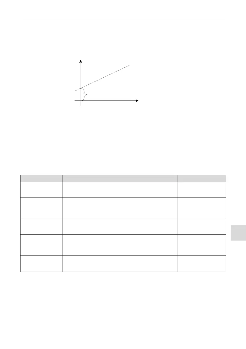
These four function parameters can dene required AO curve.
If "b" represents zero offset, "k" represents gain, "Y" represents actual output of the AO, and "X" represents
output frequency, then the actual output is
Y=kX + b.
b=F5-10
k
=F5-11
Parameter to be
output (X before
correction)
AO1 output
(Y after correction)
Figure 5-12 AO signal correction characteristic curve
Zero offset coefcient 100% of AO1 and AO2 corresponds to 10 V or 20 mA. A standard output is the value cor-
responding to 0 to 10 V or 0 to 20 mA without offset or gain.
For example, AO is used for output of frequency reference. To implement output of 8 V at 0 Hz and output of 4
V at 40 Hz, set F5-11 to -0.5 and set F5-10 to 80%.
5.10 Auto-tuning
You can obtain parameters of controlled motor through motor auto-tuning. Motor auto-tuning methods are dy-
namic auto-tuning, static auto-tuning 1, and static auto-tuning 2. You can enter the motor parameters manually.
Auto-tuning Method Application Result
Dynamic auto-tuning
with no-load
F1-37 = 2
It is applied to applications where motor can be disconnected from
load.
Best
Dynamic auto-tuning
with load
F1-37 = 2
It is applied to applications where motor cannot be disconnected
from load and dynamic auto-tuning is not allowed. The load friction
force is small and the motor is appropriately idle when running at
a constant speed.
The effect is better with
smaller friction force.
Static auto-tuning 1
F1-37 = 1
It is applied to applications where the motor cannot be
disconnected from the load and dynamic auto-tuning is not
allowed.
OK
Static auto-tuning 2
F1-37 = 3
It is applied to applications where the motor cannot be
disconnected from the load and dynamic auto-tuning is not
allowed. This mode is recommended for static auto-tuning. It
lengthens the auto-tuning time compared to static auto-tuning 1.
Better
Manual parameter
input
It is applied to applications where the motor cannot be
disconnected from the load. Copy parameters of motors of same
model which have been auto-tuned to F1-00 to F1-10.
Better