100 50 20 10 5 2 1 0.5
MAGNIFICATION FACTOR
Y
VAR M
CAL O
+
-
INCH
METRIC
100
50 20 10 5 2 1 0.5
MAGNIFICATION FACTOR
X
VAR
M
CAL O
+
-
OFF
ON
0
1
START RESET
MODE
T
50 20 10 5 2 1 0.5 0.2 0.1
125 50 25 12.5 5 2.5
1.25
0.5 0.25
s/cm
s/inch
XY
YTM
STAND
BY
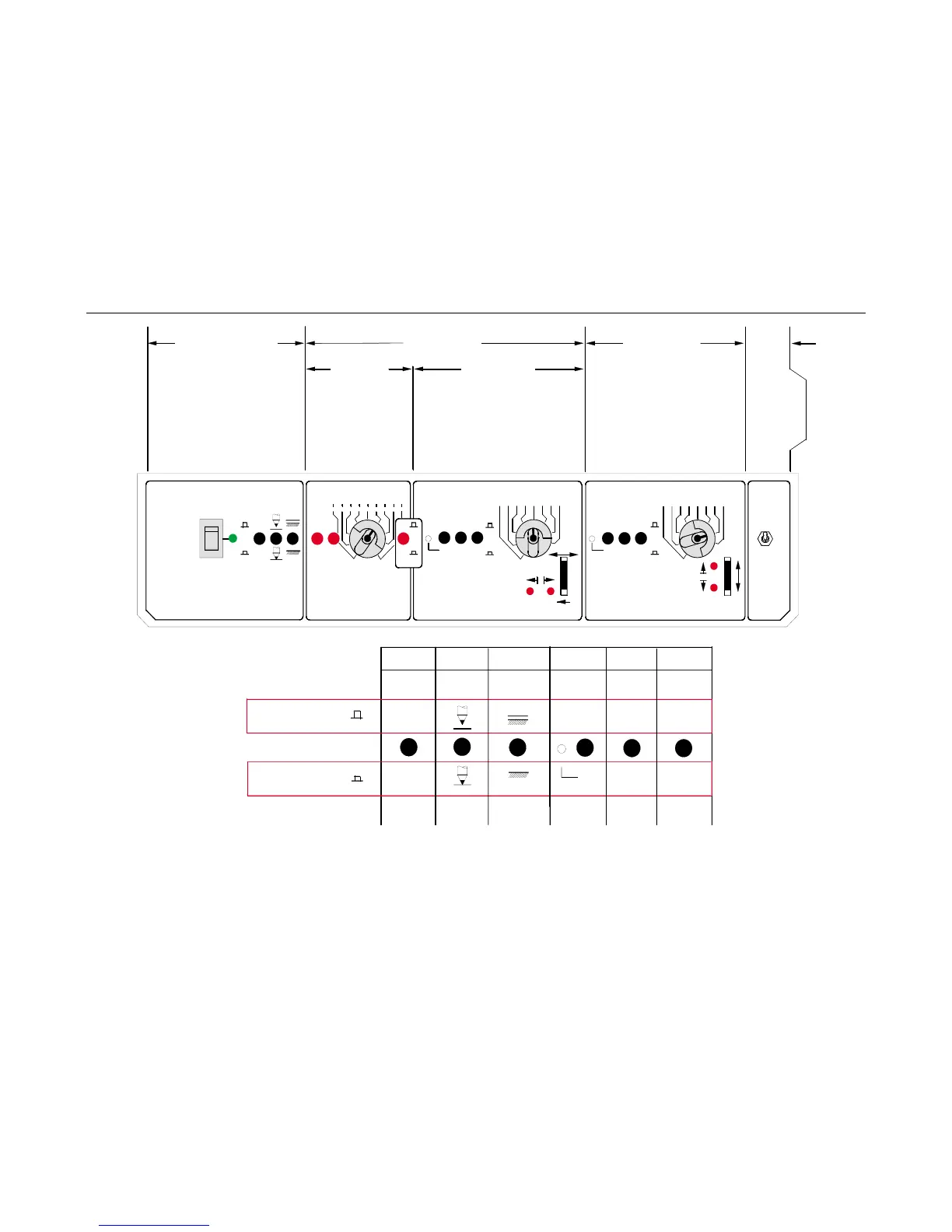
Main Control Module
X Axis Controls
YAxisControls
Calib.
Select.
These basic controls must
be addressed for input signals to
be displayed.
Time Mode
Moves Pen on
X axis from left to
right at a rate
determined by the
Time Base Selector
Switch setting.
X Servo Mode
Pen moves on X axis as a
function of an analog signal from a
transducer like an extensometer.
The Strain option must be installed
for this to function.
Positions pen on the Y axis
in response to the load force
applied to the load cell. If the
Area button is set to a value other
than its default value of 1.00, the
pen position can represent Stress.
Select switch
position to
match chart
paper
graduations
M
STAND
BY
M
O
+
-
VAR
CAL
PUSHBUTTON DOWN
Electrostatic
paper hold-down
Pen Lift
Calibrate/Variable
span switch
Polarity Switch
Enable/Disable
switch
Input disabled
pen up-right
Input enabled
Pen to Input
position
Pen Down
Pen Up
Input Disabled
Input Enabled
+ Up Y-axis
+ Rt, X-axis
-UpY-axis
- Rt, X-axis
paper hold-down
OFF
Pre-set Mag.
Factor ON
Adjustable Mag.
Factor ON
PUSHBUTTON UP
paper hold-down
ON
Stand By/
Measure switch
Figure 6-1 Model 4400 X-Y Recorder Panel
X-Y Recorder
6-17

 Loading...


