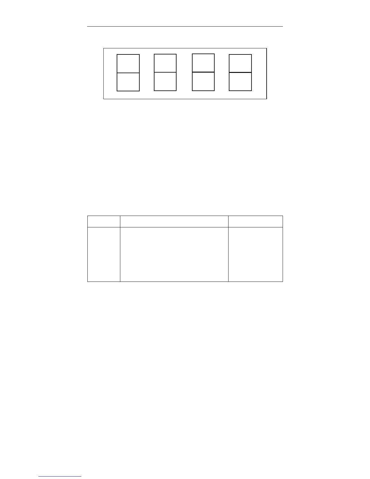
Each half of each digit in the display represents a func-
tional section in the console. The top halves are assigned
to optional sections and the bottom halves to basic sec-
tions (except Nos. 4, 7, and 8), as shown in Figure 4-4.
The numbers in each digit correspond to the listing in
Table 4-5.
Section No. Functional Name Basic or Option
1
2
3
*4
5
6
*7
8
IEEE-488 Interface
Central Processing Unit (CPU)
Crosshead Control
(Not Used)
Load Sensor Conditioner
Strain Sensor Conditioner
(Not Used)
(Not Used)
Option
Basic
Basic
--
Basic
Option
–
–
*Section No. 4 is not included in the Resident Self Test feature. It always shows in the Self
Test as “good” even though this section is not used. Sections 7 and 8 will always show as
“Not Used”.
Table 4-5. Control Console Sections
6
2
3
7
4
8
5
1
Figure 4-4. Console Section Numbers Assigned to Main
Panel Display for Self Test Result
Self Test Routine M10-94400-1
4-26

 Loading...


