Cabling for Optional Equipment
Cables
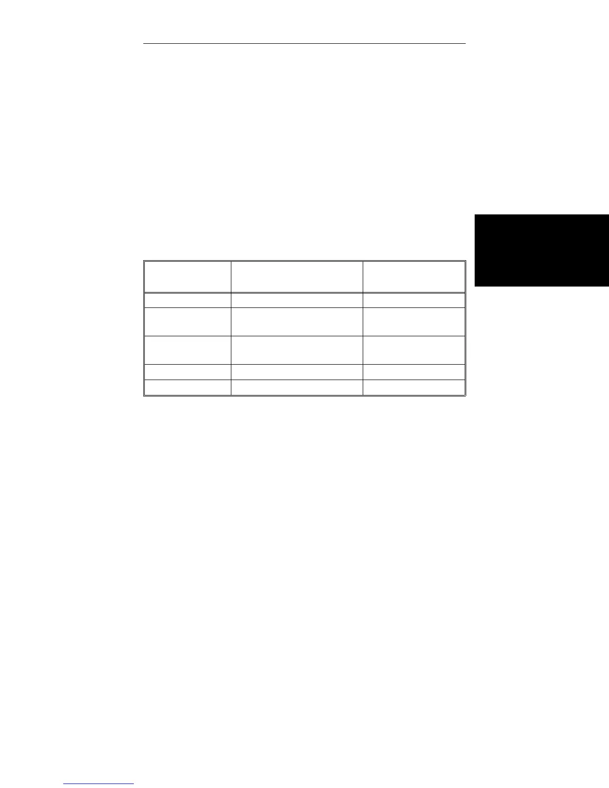
For Series 4400 systems, a recorder, printer and com-
puter connect directly to the rear panel of the console, us-
ing the cables provided with these options (see Table
3-1). The cables for load and strain measuring devices
plug into connectors on the devices themselves, as de-
scribed in the system load frame manual. Thus, you usu-
ally will not have to open the console as part of the
installation procedure.
Analog Output Connector
The Analog Output connector on the rear panel of the
console is used to connect to a chart recorder, a strip
chart recorder, or other data acquisition device. This con-
nector is a 9-pin, miniature, female “D” connector, that
has the pin assignments shown in Table 3-2.
OPTIONAL
ACCESSORY
CABLE ASSEMBLY
CONSOLE
CONNECTOR
X-Y Recorder A570-26 ANALOG OUT
Strip Chart
Recorder
A570-26 ANALOG OUT
Extensometers
(all types)
(Supplied with
Extensometer)
STRAIN
Printer (Supplied with Printer) RS-232
Computer 144-1-35 IEEE
Table 3-1. Series 4400 Console Option Cables
Installation
Console Connections
3-9

 Loading...


