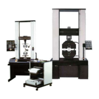
Console Components
The Series 4400 Control Console contains a single
printed circuit board on which are mounted all of the
electrical components, including the front panel
switches and displays, and rear panel connectors.
The console printed circuit board is the interface for all
connections to the console. The interconnecting cables
from the load frame and load cell, and cabling from op-
tional recorders, printers, and strain measuring devices
plug into connector locations on the rear of the board.
Since the console receives its electrical power from a
d.c. power supply in the load frame, there is no need for
bulky power supplies and cooling fans, and thus a com-
pact size has been achieved.
The Console itself is mounted on the load frame by
means of a special bracket. A friction locking device on
the bracket rides in grooves in the crosshead column cov-
ers on the load frame, allowing the console to be moved
to any convenient working height. The bracket is sym-
metrical, allowing the console to be mounted on either
the right-hand or left-hand column on the frame.
The main components of the control console are shown
in Figure 1-2. Access to the interior of the console is de-
scribed in Chapter 4.
Introduction
Console Components
1-7

 Loading...