Limits Section
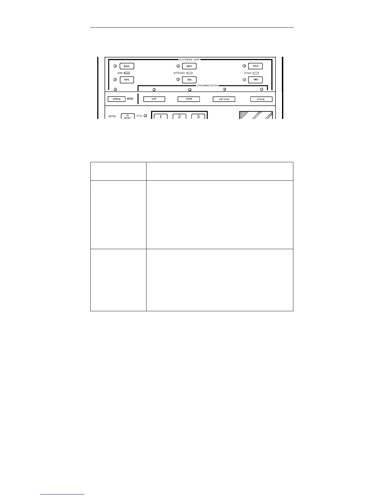
Figure 4-3. Limits Section
CONTROL or
INDICATOR
FUNCTION
LOAD MAX/MIN
EXTENSION MAX/
MIN
STRAIN MAX/MIN
BREAK
Electronic limits which permit an action to be
independently assigned to the maximum and minimum
values of load, extension or strain, or to detect break. An
LED to the left of each key lights when the key is
pressed. This shows that the key has enabled the
numeric keypad and a limit value can be entered and
viewed on the display (except BREAK, as this has an
unknown numeric value). If the Recorder is installed, the
STRAIN limits are functional only if STRAIN is selected
for the X-axis of the X-Y recorder.
OFF
STOP
RETURN
CYCLE
Crosshead actions that can be selected to occur at the
electronic limits. The actions are:
OFF - no action
STOP - stop crosshead when limit occurs
RETURN - return crosshead to gauge length
CYCLE - change crosshead travel direction
Whenever a limit key LED is lit, a CROSSHEAD ACTION
key LED is lit also. To change the action, press a different
key.
Table 4-3. Limits Section Functions
Function Of Controls M10-94400-1
4-14

 Loading...


