LED just after power on or system reset indicates a
RAM problem.
Red Latch Indicator LEDs
The latch indicators include the red CPU A RAM LED
and the red Crosshead Control FAULT LED. These
LEDs are never on except when a latch has been trig-
gered and a system reset (main power turned off and
then on) is required.
The RAM latch protects memory in case of a power fail-
ure; the POWER status indicator on the Main Panel also
lights when this occurs.
The FAULT latch prevents the crosshead drive power
amplifier from being enabled if the watchdog timer fails;
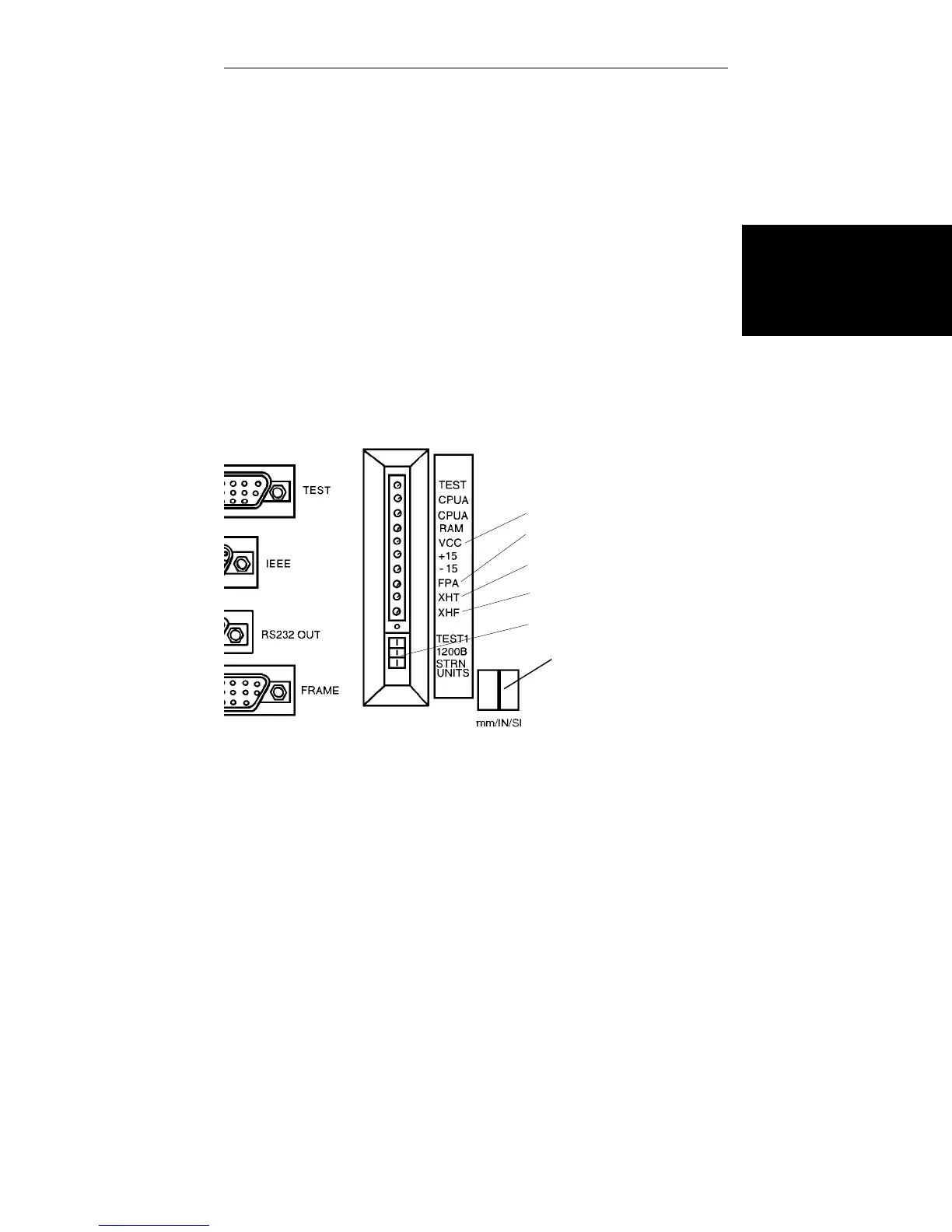
FRONT PANEL ACTIVE
CROSSHEAD TEST
CROSSHEAD FAULT
+5V POWER SUPPLY
DIP SWITCHES
SYSTEM UNITS SWITCH
Figure 8-2. Closeup Detail of Console Status and Fault
Indicators
Maintenance
Rear Panel Indicators
8-13

 Loading...


