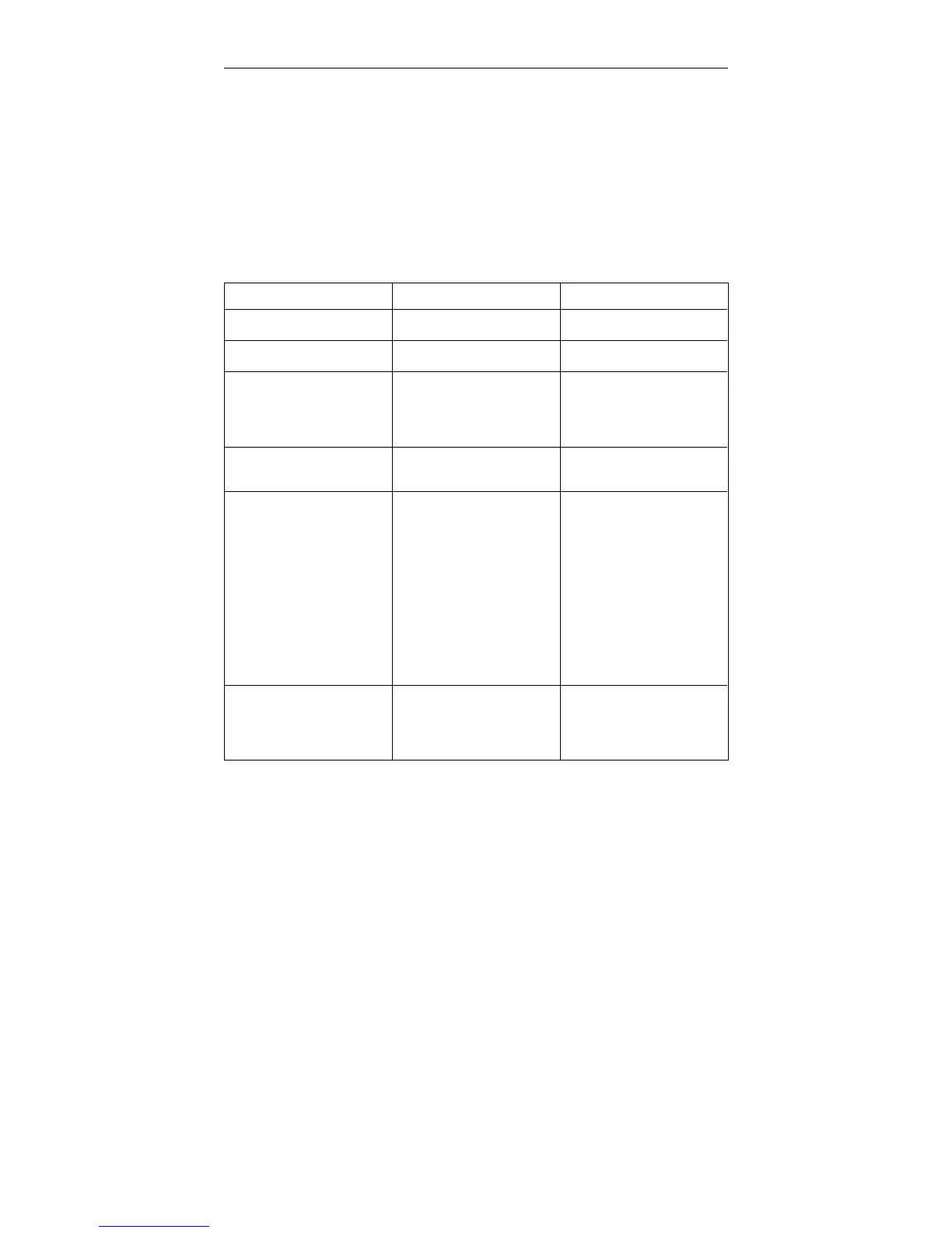
Fault Indications
The fault indicators on the Main Panel light under cer-
tain conditions occurring during system operation. The
chart below lists the probable cause of these conditions
and the action to be taken.
FAULT INDICATOR CAUSE CORRECTIVE ACTION
POWER
(Drive disabled)
Momentary power loss. Cycle power off/on.
TIMER
Drive disabled)
CPU malfunctions or loss of
+/- 15 Vd.c. power.
Cycle power off/on. Note
Self Test result.
LOAD (flashes)
(Crosshead stops)
Load overrange greater than
102% of cell capa- city with
AREA ≅ 1; or greater than
115% if AREA is set much
larger than 1.
Reduce load by UP, DOWN
or JOG keys (only proper
direction is en- abled).
Indicator flashes until a new
test is started.
TRAVEL
(Crosshead stops)
Upper or lower crosshead
travel limit reached
Back off from limit by UP,
DOWN or JOG keys (only
proper direction is enabled).
MOTOR
(Drive disabled.
Indicator on steady.)
1. Motor drive enabling se-
quence (5 sec. duration)
2. Motor drive cannot be
enabled.
3. Load frame cannot be
identified.
4. Load frame power supply
failure.
5. Crosshead second level
travel limit tripped.
6. Emergency stop switch
tripped.
7. Door interlock open.
Wait 5 sec. If speed shows
as “———-”, check frame-to-
console cabling. Do a
System reset.*
MOTOR
(Drive disabled.
Indicator flashing.
1. Drive motor overheated.
2. Drive loop failure.
3. Drive stall.
Do a system reset.* If flash-
ing restarts, allow motor to
cool and reset*. Check for a
mechanical jam if fault
persists (requires service).
*
To reset system, cycle power off/on or perform the key sequence [S1] [0] [ENTER] which
clears memory, or the sequence [S1] [1] [ENTER] which saves current memory.
Table 8-4. Fault Indications
Fault Indications M10-94400-1
8-16

 Loading...


