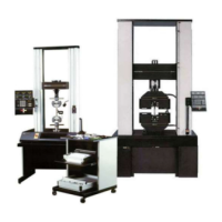
Front Panel
The Front Panel (Figure 1-2) is divided into four major
sections. The Main section contains a numeric keypad
for data entry of system setup parameters, an LCD dis-
play for the numeric input, pushbuttons for such func-
tions as crosshead speed selection, and gauge length
setting, among others. The Display section contains
LCD displays of real-time values of Load, Extension,
and Strain, while the Limits section sets electronic limits
for the system. The last section is the Crosshead Control
section, in which manual controls for crosshead position-
ing are located.
Main Panel Section
The Main Panel section consists of test function entry
keys, a numeric keypad and a 4-digit LCD display.
Status indicators on the left-hand side of the panel, when
lit, signify that a fault has occurred. The current units
(S.I., English, metric) in use by the testing system are
also shown in this area. The panel provides the follow-
ing functions:
• Load cell calibration
• Crosshead speed selection
• Gauge length
• Area compensation
• Testing area definition
• Strain transducer calibration
• Printer operation
• IEEE bus enable/disable
• Special Software - Diagnostics
Front Panel M10-94400-1
1-8

 Loading...