The pinout appears as follows, looking at the connector:
54321
9876
The Load and Strain output pin signals are ±10 volts,
relative to Analog Ground. +10 volts corresponds to ten-
sion full scale.
The PIP pin connection is an active low TTL signal rela-
tive to Digital Ground. The signal is driven by a contact
closure fed into the Pip Jack on the console.
The Run pin connection is an active high TTL signal
relative to Digital Ground. The signal goes high when a
test is running.
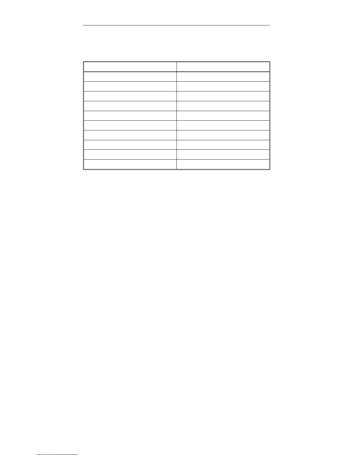
Pin Number Signal
Metal Shell Chassis Ground
1 Load
2 Strain
3 No Connection
4 Pip
5 Run
6 Analog Ground
7 Analog Ground
8 Digital Ground
9 No Connection
Table 3-2. Analog Output Connector Pin Assignments
Console Connections M10-94400-1
3-10

 Loading...


