(g) If a non-self identified transducer is installed, hang a
precision weight, within the range of the load cell,
from the cell, or displace the extensometer with the
calibrator, and observe the pen deflection.
(h) Adjust the CAL variable control on the recorder to
set the pen to exactly the value of the precision
weight or extensometer deflection.
Time Base Operation
You can use the X-Y Recorder in a time-based mode, if de-
sired. The Y-Axis signal is plotted against a recorder-gener-
ated time base which can be correlated with crosshead
speed. The time scale can be switch-selected for a range of
0.1 seconds per centimeter to 50 seconds per centimeter or
0.25 seconds per inch up to 125 seconds per inch.
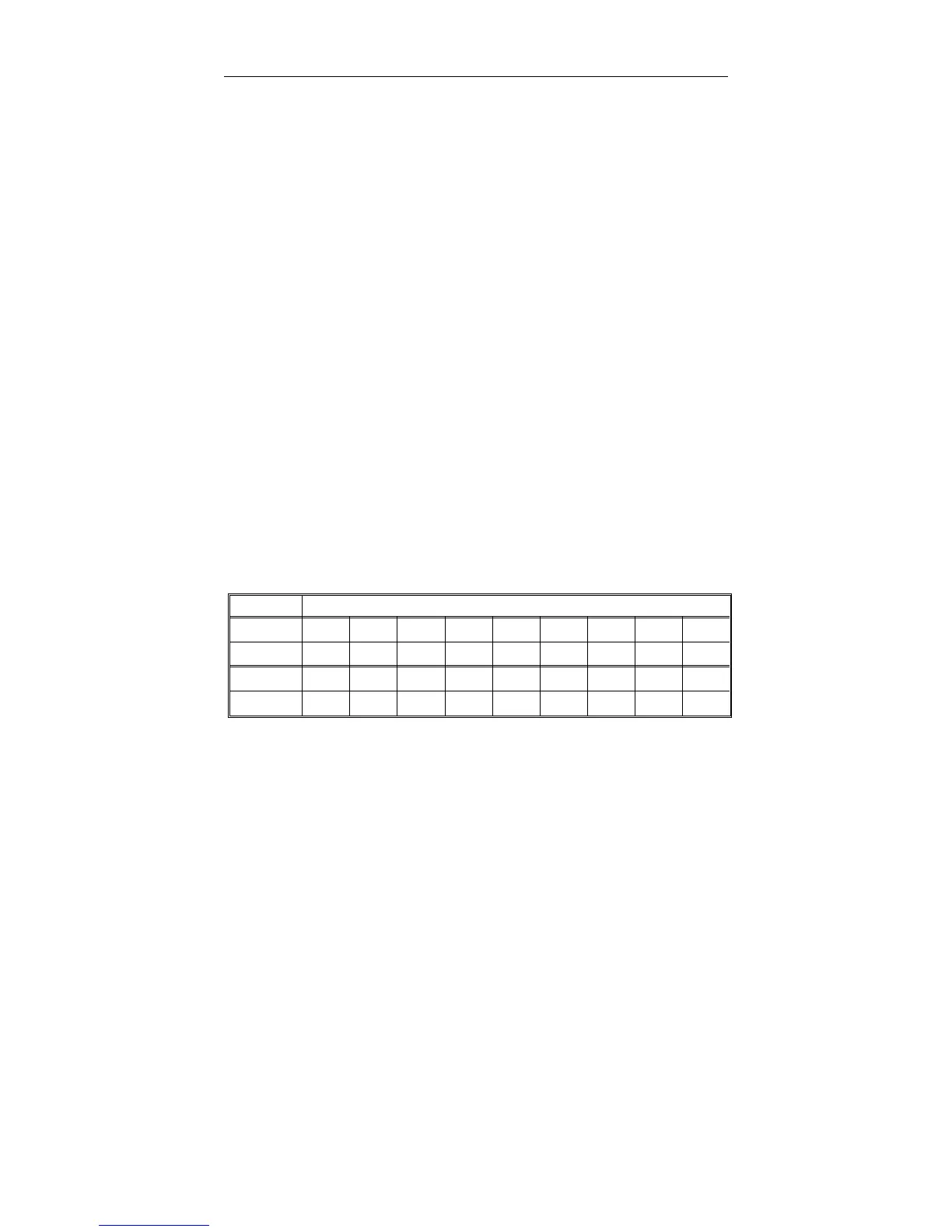
Since the Model 5500 uses chart speeds in units of
inches/minute or centimeters/minute, and the Recorder
Time Scale is in units of seconds/inch or seconds/centime-
ter, Table 6-5 gives speed conversions between the two.
To set up the Time Base on the Recorder, do the following:
(a) Press the X-Y/Y-T MODE switch down to Y-T.
Chart Speeds
Sec/In 0.25 0.5 1.25 2.5 5 12.5 25 50 125
In/Min 240 120 48 24 12 4.8 2.4 1.2 0.48
Sec/Cm 0.1 0.2 0.5 125102050
Cm/Min 600 300 120 60 30 12 6 3 1.2
Table 6-5. Chart Speed Conversions
X-Y Recorder M10-94400-1
6-22

 Loading...


