Control Head Components
Replacement Procedures
CUSA EXcel Ultrasonic Surgical Aspirator System Service Manual 11-19
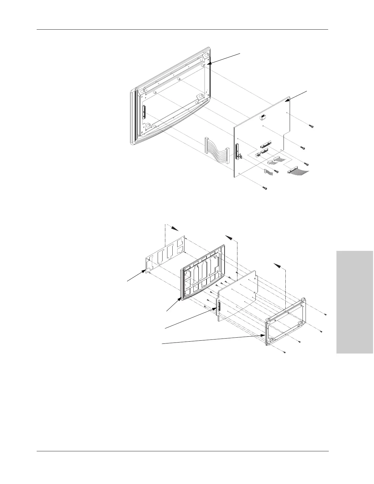
Figure 11-10.
Disconnecting the 50-pin ribbon cable
and removing the Machine Control
PCB
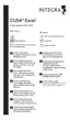
Figure 11-11.
Removing the Display PCB from the
control head assembly
Install the Display PCB
1. Attach the display PCB to its chassis:
a. Position the display PCB onto the chassis.
b. Replace the eight screws (M4 Phillips) in the display PCB.
2. Being careful to make sure the silicon buttons clear the bezel, position the
display PCB and chassis in the control panel bezel.
Machine
Control PCB
Machine
Control PCB
Control panel
overlay
Control panel
bezel
Display PCB
Chassis