Suction Control Valve
Replacement Procedures
CUSA EXcel Ultrasonic Surgical Aspirator System Service Manual 11-27
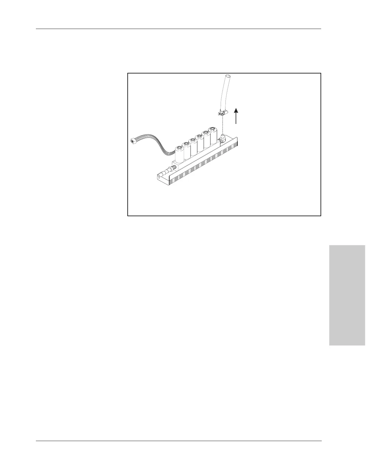
6. Remove 3/8 in. ID suction tube and clamp from the suction control valve: Set
them aside for re-use.
Note: The new suction control valve does not include this tube and clamp.
Figure 11-19.
Removing the suction hose and clamp
from the suction control valve
Install the Suction Control Valve
Assemble the Suction Control Valve to the Manifold Bracket
1. Attach the 3/8 in. ID suction tube and clamp to the suction control valve.
2. Attach the suction control valve to the manifold bracket:
a. Position the suction control valve inlet screen on the manifold bracket so
that its three holes align with the three screw holes in the bracket.
b. Position the suction control valve on the manifold bracket so that its three
holes align with the three screw holes in the inlet screen and bracket.
c. Replace three screws (M4 socket head cap screws) in the suction control
valve.
Note: A lock washer secures the screw on each end of the assembly, but no
lock washer secures the third screw.