EasyManua.ls Logo

Integra Cusa Excel Service Manual

Integra Cusa Excel
213 pages
To Next Page IconTo Next Page
To Previous Page IconTo Previous Page
Page #146 background image
Ultrasonics and Machine Control Printed Circuit Boards
Replacement Procedures
CUSA EXcel Ultrasonic Surgical Aspirator System Service Manual 11-11
Install the Ultrasonics PCB
1. Place the new ultrasonics PCB assembly near the CUSA EXcel console. Insert
the following ultrasonic PCB fan assembly lead wires into the 6-pin fan
connector housing:
Refer to Table 11-2 and Figure 11-4.
2. Position the ultrasonics PCB assembly in the CUSA EXcel console.
3. Replace four screws (M5 Phillips) and four lock washers (M5) on the
ultrasonics PCB panel.
4. On the new ultrasonics PCB assembly, the header at J6 (syphon valve) has a
3.96 mm (0.156 in.) center. The CUSA EXcel console syphon valve lead
wires terminate in a 2-pin connector with either a 3.96 mm (0.156 in.) or a
2.54 mm (0.100 in.) center.
 If the connector for the console syphon valve has a 3.96 mm (0.156 in.)
center, connect it to the ultrasonics PCB assembly at J6.
OR
 ONLY IF the connector for the console syphon valve has a 2.54 mm
(0.100 in.) center, plug the syphon valve cable assembly adapter into the
connector, then connect the adapter/connector assembly to the ultrasonics
PCB assembly at J6. Refer to Figure 11-5.
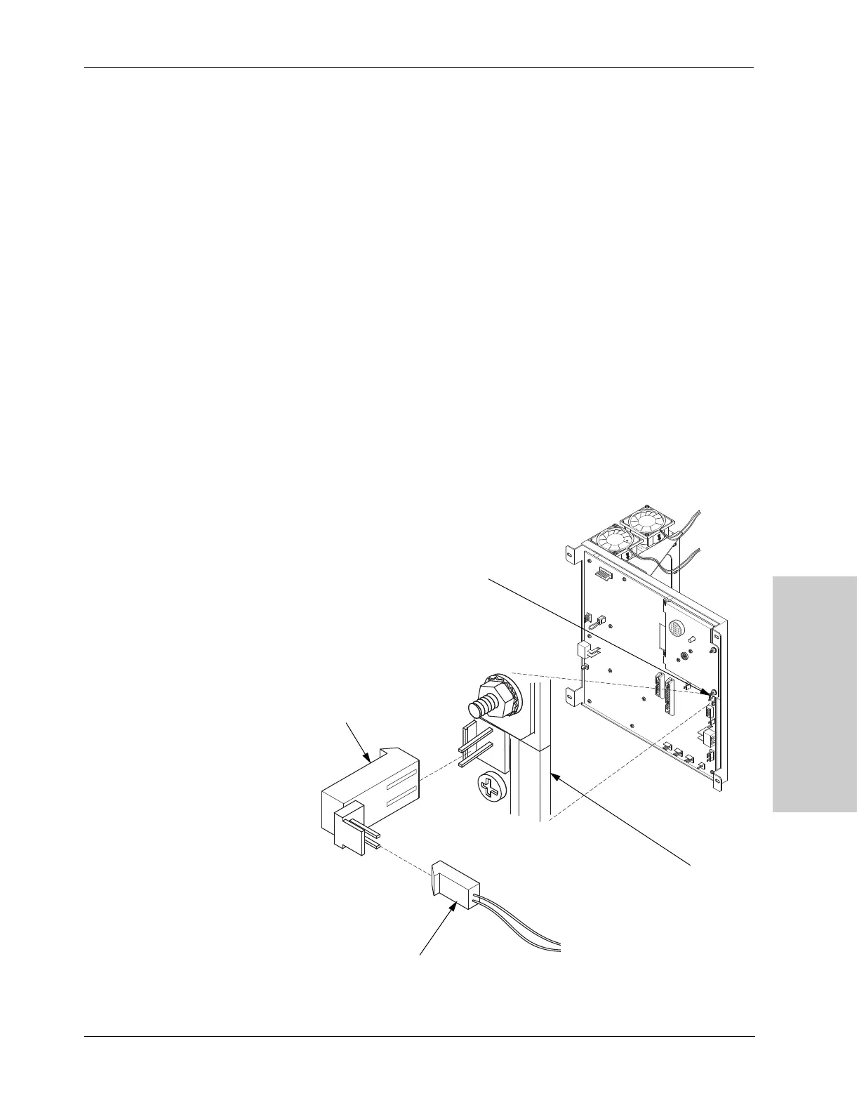
Figure 11-5.
Plugging the adapter for the syphon
valve cable assembly into the
connector at J6 on the ultrasonics
PBC
J6
J6 Detail
Adapter for syphon
valve cable
assembly
Syphon valve connector

Table of Contents

Other manuals for Integra Cusa Excel

Question and Answer IconNeed help?

Do you have a question about the Integra Cusa Excel and is the answer not in the manual?

Integra Cusa Excel Specifications

General IconGeneral
BrandIntegra
ModelCusa Excel
CategoryMedical Equipment
LanguageEnglish

Summary

Service Personnel Safety

Safety Information and Warnings

General safety guidelines, warnings, cautions, and notices for servicing.

Operational Procedures and Guidelines

Instructions for unpacking, installation, maintenance, and troubleshooting.

Introduction

System Overview and Components

Describes the CUSA EXcel system, its functions, and main components.

Principles of Operation

Explains how the handpiece, fragmentation, cooling, and TissueSelect feature work.

Unpacking and Installation

Unpacking Procedures

Step-by-step guide for safely unpacking the CUSA EXcel system from its crate.

Console Setup and Power Connection

Instructions for preparing the console and connecting the power.

Console Components

Console Layout and Features

Details the physical layout and structural features of the CUSA EXcel console.

Control Panel Functions and Indicators

Explains control panel buttons, displays, alerts, and status indicators.

Component Descriptions

Details specific components like front, side, and rear panels, and their parts.

Technical Specifications

Console Dimensions and Subsystems

Provides dimensions for console/footswitch and specifications for subsystems.

Electrical, Environmental, and Safety Standards

Covers electrical requirements, operating environment, and relevant safety standards.

Handpiece and Tip Specifications

Details specifications for handpieces and various surgical tips.

Circuit Theory

Display Board and Machine Control Board Circuits

Explains the circuitry of the display and machine control boards.

Ultrasonics Board and Power Supply Circuits

Details the ultrasonics generator, other circuits, and the power supply board.

Checkout Procedures

Pre-operation Inspections

Covers inspections of the footswitch, power cord, and power-on verification.

Handpiece Functional Test

Step-by-step guide for testing the handpiece functionality.

Maintaining the CUSA EXcel System

Recommended Maintenance Schedule

Outlines routine maintenance tasks, frequency, and equipment.

Cleaning and Component Maintenance

Procedures for cleaning the console, sterilizer case, and maintaining the handpiece.

Tip Torquing and System Storage

Covers maintaining the tip torquing set and proper system storage.

Troubleshooting

Troubleshooting Safety and User Guide

Safety precautions and user-level troubleshooting for common issues and alerts.

Engineer Troubleshooting and Flowcharts

Advanced troubleshooting steps and diagnostic flowcharts for engineers.

Replacement Procedures

Console Cover and Power Supply Replacement

Procedures for replacing console covers and the 24V power supply.

PCB and Control Head Component Replacement

Steps for replacing PCBs and control head components.

Pump, Valve, and Sensor Replacements

Procedures for replacing suction control valve, pump, pinch valve, flow sensor.

Cooling Water System and Fuse Replacements

Procedures for replacing cooling water tubing, O-rings, and fuses.

Calibration

Calibration Tools and Setup Procedures

Lists necessary tools and initial setup for calibrations.

Pump and Motor Calibration

Calibration procedures for the suction pump and cooling water pump motor.

Repair Policy

Equipment Return and Packaging Procedures

Guidelines for returning equipment, obtaining authorization, and packaging.

Parts Ordering and Service Center Information

How to order parts and contact Integra service centers.

Service Parts Lists

Parts Identification and Ordering

Information on identifying and ordering replacement parts.

Component Parts Breakdown

Lists parts for handpiece cooling, irrigation, power, suction, electronics, mechanics.

Warranty

Product Warranty Terms and Coverage

Details Integra's warranty, coverage, and exclusions for the equipment.

Service, Repairs, and Liability Limits

Outlines terms for service, repairs, and limitations of liability.

Related product manuals