Display Board
Circuit Theory
CUSA EXcel Ultrasonic Surgical Aspiration System Service Manual 7-3
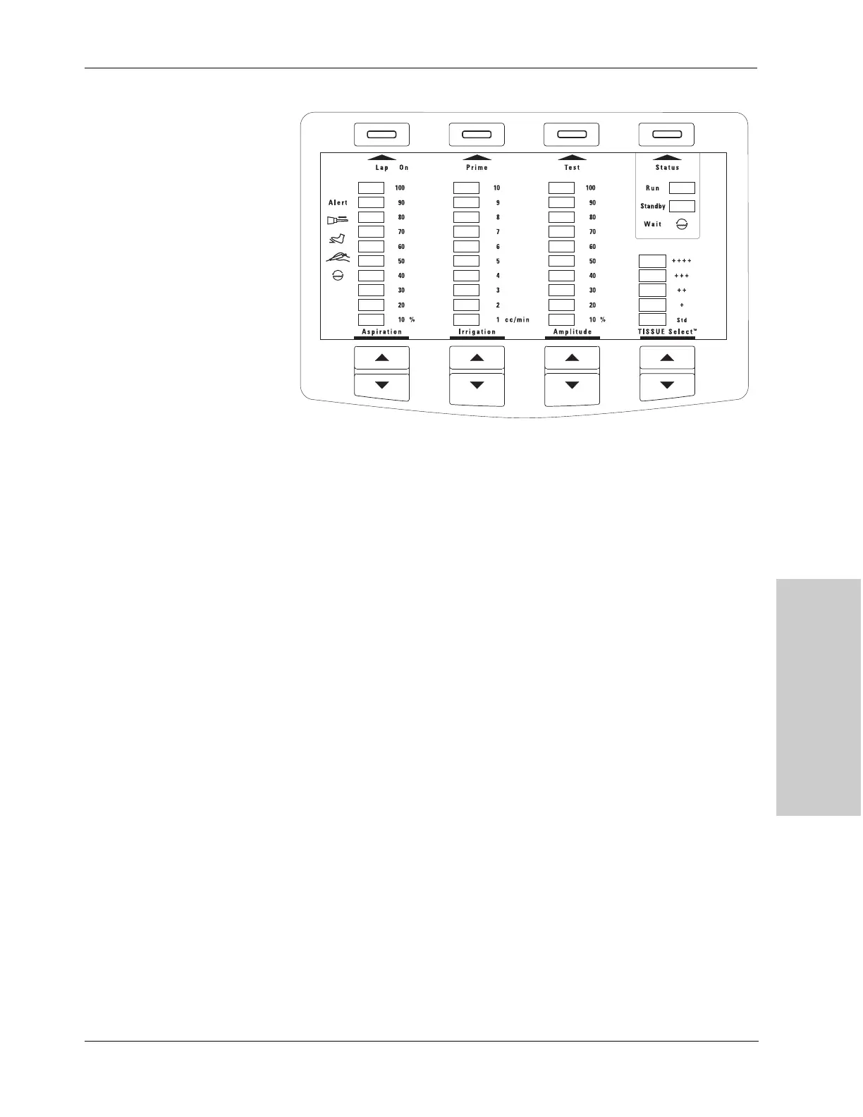
Figure 7-1.
The display organization on the
control panel
Due to the quantity of LEDs, space restriction, and heating considerations, FET
switches connected to a multiplexing display driver (Maxim 7218) drive the
displays. A resistor in series with the LED light bar limits current through the
LEDs. A P-channel FET sources the voltage to the resistor and LED light bar
series combination. An N-channel FET sinks the current to ground from the LED
light bars. The outputs of the 7218 display driver control the gates of the FETs.
To reduce the number of display drivers and the quantity of logic code, a coded
map identifies each individual LED light bar location so that a single display
driver can control all of the amplitude, irrigation, TissueSelect, and aspiration
displays. A second display driver controls the number legends, the alerts, the
status indicators, and the button indicators.
Detailed Circuit Description
Each “circuit” works the same way. It simply repeats several times to allow
individual control over each light bar package. The following description details
the circuit for the aspiration column at a setting of 10%.
The 7218 display driver (U3) receives inputs from the machine control board via
the 50 pin ribbon cable connector, J1. The segment output of the display driver
connects to a 1k pull-up resistor (RA2) and the gate of an N-channel FET (U66).
The source of the FET ties to +5Vin and the drain connects to a resistor network
(RA32). Several of the resistors are tied together to achieve an average current of
12 mA through each LED of the light bar for a total of 96 mA per light bar. The
resistors, in parallel, connect in series with the light bar (U221). All diodes in the
light bar connect in parallel. The cathode of the diode connects to the drain of the
N-channel FET (U65). The source of U65 connects to ground. The gate connects
to a digit output of U3 and a pull-down resistor (RA6).
For any light bar to be illuminated, it must receive both the correct segment and
digit output from the display driver. Each LED light bar (except for the numeric
legends) has a unique map location; thus, each LED light bar is independently
controlled. The numeric legends are controlled together, not independently.