Ultrasonics and Machine Control Printed Circuit Boards
11-10 CUSA EXcel Ultrasonic Surgical Aspirator System Service Manual
6. Remove the ultrasonics PCB assembly from the console. Place the ultrasonics
PCB assembly on the floor next to the console.
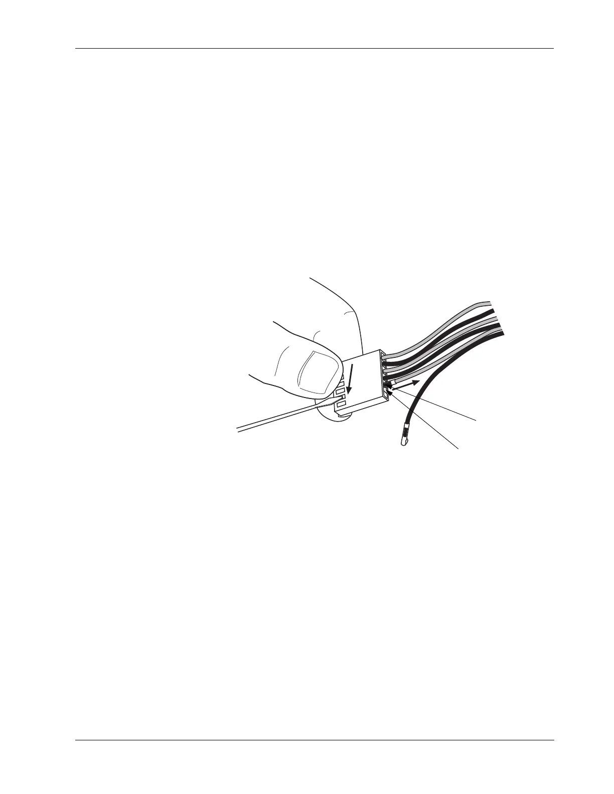
7. Disconnect the ultrasonics PCB fan assembly by removing the following lead
wires from the 6-pin fan connector housing (removed from J14). Refer to
Figure 11-4.
Table 11-2.
Ultrasonics PCB fan assembly
connectors
Figure 11-4.
The ultrasonics PCB fan assembly
connections
Color Pin
red 5
black 6
Red wires appear
gray in this graphic
Pin 5 (red wire)
Pin 6 (black wire)