Ultrasonics and Machine Control Printed Circuit Boards
Replacement Procedures
CUSA EXcel Ultrasonic Surgical Aspirator System Service Manual 11-9
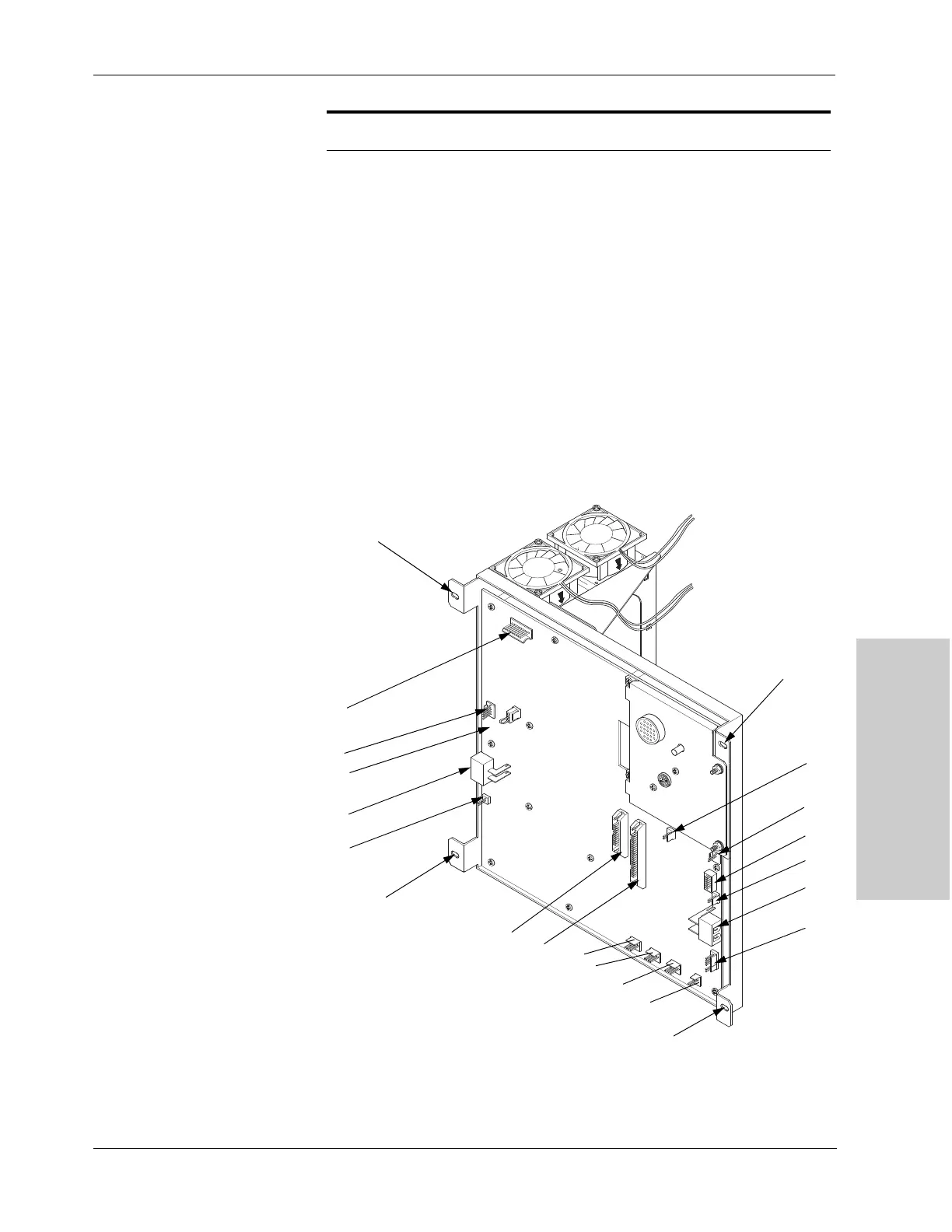
5. Remove four screws (M5 Phillips) and four lock washers (M5) from the
ultrasonics PCB panel. Refer to Figure 11-3.
When you remove the ultrasonics PCB panel, you will find the heat sink and
cooling fan cables attached to it.
Figure 11-3.
Cables on the ultrasonics PCB
assembly
J14 6-pin connector red, black, red, black, red, black
J13 large 2-pin connector orange, brown
J10 small 2-pin connector brown, orange
J7 12-pin connector black
J6 2-pin connector black, black
J5 2-pin connector green, white
Loc. Connector Wire Color
J11
J9
J8
J12
M5 Phillips screw
J13
J7
J6
J3
J5
M5 Phillips screw
J1
J4
J15
J16
J17
J18
J14
J10
M5 Phillips screw
M5 Phillips screw