Intel
®
Server Board S2600CP and Server System P4000CP TPS
Intel® Server Board S2600CP Connector/Header Locations and Pin-outs
Revision 1.1
Intel order number G26942-003
87
7. Intel
®
Server Board S2600CP Connector/Header
Locations and Pin-outs
7.1 Power Connectors
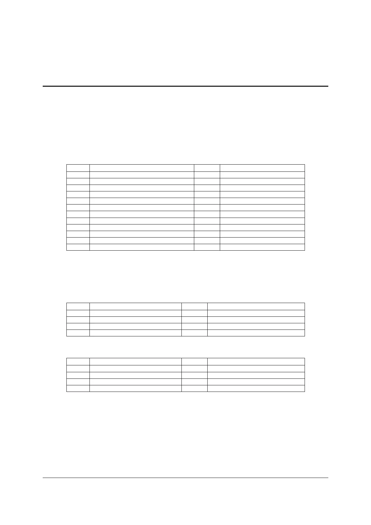
7.1.1 Main Power Connector
Main server board power is supplied by one 12-pin power connector. The connector is labeled
as “MAIN PWR” on the left bottom of the server board. The following tables provide the pin-out
for “MAIN PWR” connector.
Table 26. Main Power Connector Pin-out
Pin Signal name Pin Signal name
1 P3V3 13 P3V3
2 P3V3 14 N12V
3 GND 15 GND
4 P5V 16 FM_PS_EN_PSU_N
5 GND 17 GND
6 P5V 18 GND
7 GND 19 GND
8 PWRGD_PS_PWROK_PSU_R1 20 NC_PS_RES_TP
9 P5V_STBY_PSU 21 P5V
10 P12V 22 P5V
11 P12V 23 P5V
12 P3V3 24 GND
7.1.2 CPU Power Connectors
On the server board are two white 8-pin CPU power connectors labeled “CPU_1 PWR” and
“CPU_2 PWR”. The following table provides the pin-out for both connectors.
Table 27. CPU_1 Power Connector Pin-out
Pin Signal name Pin Signal name
1 GND 5 P12V1
2 GND 6 P12V1
3 GND 7 P12V3A
4 GND 8 P12V3A
Table 28. CPU_2 Power Connector Pin-out
Pin Signal name Pin Signal name
1 GND 5 P12V2
2 GND 6 P12V2
3 GND 7 P12V3B
4 GND 8 P12V3B
7.2 Front Panel Header and Connectors
The server board includes several connectors that provide various possible front panel options.
This section provides a functional description and pin-out for each connector.

 Loading...


