Intel
®
Server Board S2600CP and Server System P4000CP TPS
Intel
®
Server System P4000CP Front Control Panel and Back Panel
Revision 1.1
Intel order number G26942-003
107
ID Button with integrated ID LED – Toggles the integrated ID LED and the Blue server board
ID LED on and off. The ID LED is used to identify the system for maintenance when installed in
a rack of similar server systems. The ID LED can also be toggled on and off remotely using the
IPMI “Chassis Identify” command which will cause the LED to blink for 15 seconds.
NMI Button – When the NMI button is pressed, it puts the server in a halt state and issues a
non-maskable interrupt (NMI). This can be useful when performing diagnostics for a given issue
where a memory download is necessary to help determine the cause of the problem. To prevent
an inadvertent system halt, the actual NMI button is located behind the Front Control Panel
faceplate where it is only accessible with the use of a small tipped tool like a pin or paper clip.
Network Activity LEDs (NIC LED) – The Front Control Panel includes an activity LED indicator
for each on-board Network Interface Controller (NIC). When a network link is detected, the LED
will turn on solid. The LED will blink once network activity occurs at a rate that is consistent with
the amount of network activity that is occurring.
System Reset Button – When pressed, this button will reboot and re-initialize the system.
System Status LED – The System Status LED is a bi-color (Green/Amber) indicator that shows
the current health of the server system. The system provides two locations for this feature; one
is located on the Front Control Panel, the other is located on the back edge of the server board,
viewable from the back of the system. Both LEDs are tied together and will show the same state.
The System Status LED states are driven by the on-board platform management sub-system.
System Power Button with power LED – Toggles the system power on and off. This button
also functions as a sleep button if enabled by an ACPI compliant operating system. Pressing
this button will send a signal to the iBMC, which will either power on or power off the system.
The integrated LED is a single color (Green) and is capable of supporting different indicator
states as defined in the following table.
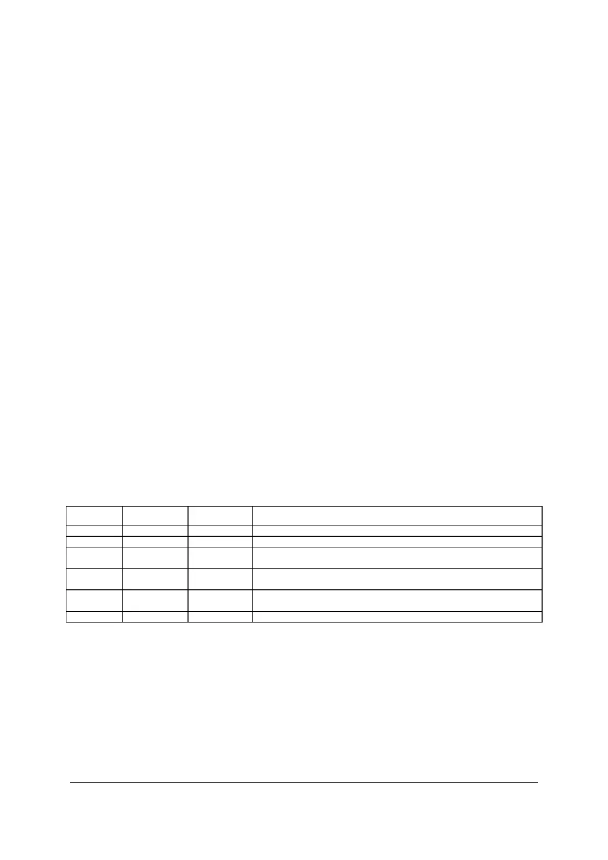
Table 57. Power/Sleep LED Functional States
State Power Mode LED Description
Power-off Non-ACPI Off System power is off, and the BIOS has not initialized the chipset.
Power-on Non-ACPI On System power is on
S5 ACPI Off Mechanical is off, and the operating system has not saved any context
to the hard disk.
S4 ACPI Off Mechanical is off. The operating system has saved context to the hard
disk.
S3-S1 ACPI Slow blink
DC power is still on. The operating system has saved context and
gone into a level of low-power state.
S0 ACPI Steady on System and the operating system are up and running.
HDD Activity LED - The drive activity LED on the front panel indicates drive activity from the
on-board hard disk controllers. The server board also provides a header giving access to this
LED for add-in controllers.
USB Ports – In addition, the front panel provides two USB ports. The USB ports are cabled to
the 2x5 connector on the server board.

 Loading...


