Intel
®
Server Board S2600CP and Server System P4000CP TPS
Intel
®
Server System P4000CP Storage and Peripheral Drive Bays
Revision 1.1
Intel order number G26942-003
117
Each connector on the SAS expander card can be used as a “cable in” (SAS Controller to SAS
Expander) or “cable out” (SAS Expander to Hot Swap Backplane) type connector.
Note: Current SCU controller design limitations prevent any hard drive attached to a SAS
expander card from being a boot device when all SCU connectors are attached to the SAS
expander card.
For storage configurations that require utilizing a hard disk drive as the boot device, the system
must be cabled as follows to ensure a boot device is found and for contiguous drive mapping (0-
16).
The SCU port 0-3 (labeled as “SAS 0” through “SAS 3”) connector on the server board is
cabled to the first mini-SAS connector on the hot swap backplane
The SCU port 4-7 (labeled as “SAS 4” through “SAS 7”) connector on the server board is
cabled to Connector A on the SAS expander card.
Cables from the SAS Expander to the hot swap backplane must be connected in order
from connector B to connector F.
11.4 Optical Drive Support
The Intel
®
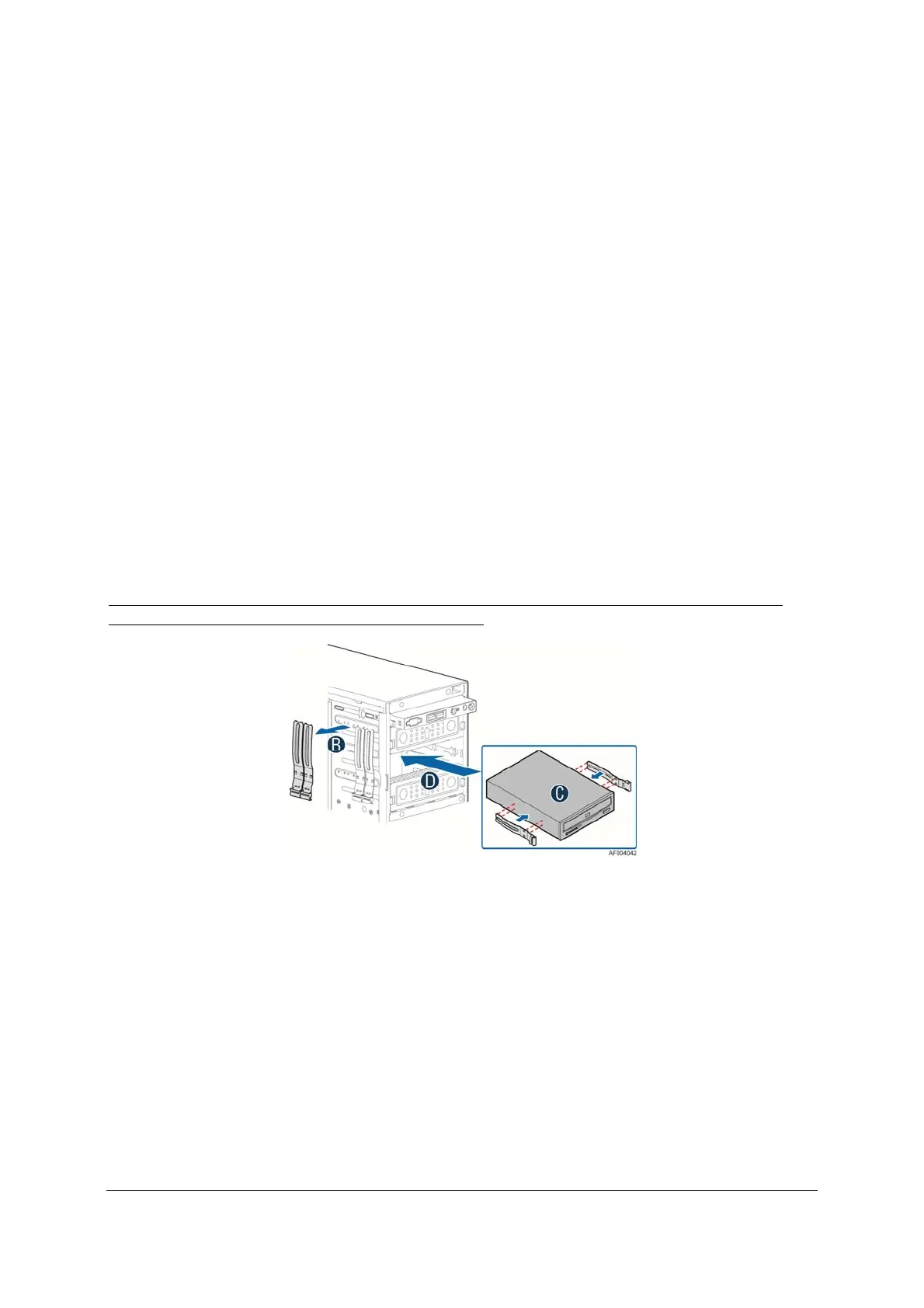
Server System P4000CP includes support three 5.25” optical drive bays. The optical
drives can be installed to one of the three drive bays as illustrated below.
Note: The data cables from optical drives are recommended to connect to the two SATA 6G
connectors (white connectors) on the server board.
Figure 47. Optical Drive
11.5 Low Profile eUSB SSD Support
The system provides support for a low profile eUSB SSD storage device. A 2mm 2x5-pin
connector labeled “eUSB SSD” is used to plug these small flash storage devices.

 Loading...


