Intel
®
Server System P4000CP Power System Options Intel
®
Server Board S2600CP and Server System P4000CP TPS
Revision 1.1
Intel order number G26942-003
130
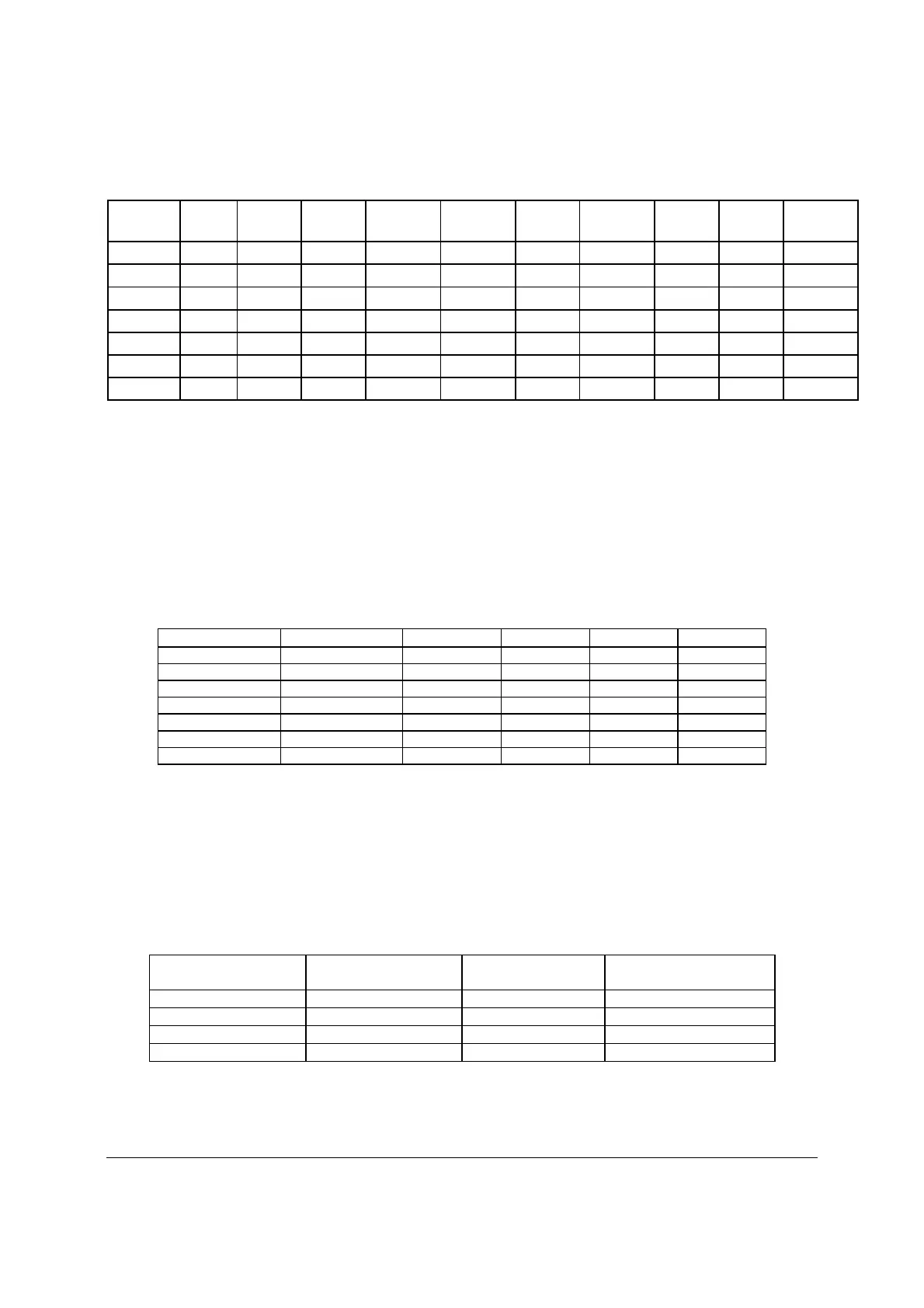
Table 77. Loading Conditions
3.3V 5.0V 12V1 12V2 12V3 -12V 5.0V
stby
Total
Power
12V
Power
3.3V/5V
Power
Load1
18 12.1 12 12 11.7 0 0.3 550 428 120
Load2
13.5 15 12 12 11.2 0.5 0.3 549 422 120
Load3
2.5 2 20 20 4.2 0 0.3 550 530 18
Load4
2.5 2 13.1 13.1 18 0 0.3 550 530 18
Load5
0.5 0.3 15 15 6.5 0.5 3 462 438 3
Load6
16 4 1 1 3.5 0 0.3 140 66 73
Load7
16 13 1 1 9 0.5 3 271 132 118
13.2.5.3 Standby Output
The 5VSB output is present when an AC input greater than the power supply turn on voltage is
applied.
13.2.5.4 Voltage Regulation
The power supply output voltages stay within the following voltage limits when operating at
steady state and dynamic loading conditions. These limits include the peak-peak ripple/noise.
These shall be measured at the output connectors.
Table 78. Voltage Regulation Limits
Parameter Tolerance Min Nom Max Units
+3.3V - 3%/+5% +3.20 +3.30 +3.46 Vrms
+5V - 4%/+5% +4.80 +5.00 +5.25 Vrms
+12V1 - 4%/+5% +11.52 +12.00 +12.60 Vrms
+12V2 - 4%/+5% +11.52 +12.00 +12.60 Vrms
+12V3 - 4%/+5% +11.52 +12.00 +12.60 Vrms
- 12V - 10%/+10% - 13.20 -12.00 -10.80 Vrms
+5VSB - 4%/+5% +4.80 +5.00 +5.25 Vrms
13.2.5.5 Dynamic Loading
The output voltages remain within limits specified for the step loading and capacitive loading
specified in the table below. The load transient repetition rate is tested between 50Hz and 5kHz
at duty cycles ranging from 10%-90%. The load transient repetition rate is only a test
specification. The step load may occur anywhere within the MIN load to the MAX
load conditions.
Table 79. Transient Load Requirements
Output Step Load Size
(See note 2)
Load Slew Rate Test capacitive Load
+3.3V 6.0A
0.5 A/
sec 970 F
+5V 4.0A
0.5 A/
sec 400 F
12V1+12V2 +12V3 23.0A
0.5 A/
sec 2200 F
1,2
+5VSB 0.5A
0.5 A/
sec 20 F
Notes:
1. Step loads on each 12V output may happen simultaneously.
2. The +12V should be tested with 2200F evenly split between the four +12V rails.
3. This will be tested over the range of load conditions in section 13.2.5.2.

 Loading...


