Intel® Server Board S2600CP Connector/Header Locations and Pin-outs
Intel
®
Server Board S2600CP and Server System P4000CP TPS
Revision 1.1
Intel order number G26942-003
88
7.2.1 Front Panel Header
Included on the left edge of the server board is a 30-pin header consists of a 24-pin SSI
compatible front panel header and a 4-pin header to support optional NIC3/4 LEDs. The 24-pin
SSI front panel header provides various front panel features including:
Power/Sleep Button
System ID Button
NMI Button
NIC Activity LEDs
Hard Drive Activity LEDs
System Status LED
System ID LED
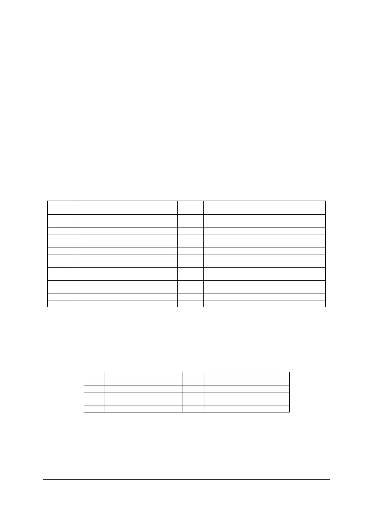
The following table provides the pin-out for this 30-pin header.
Table 29. Front Panel Header Pin-out
Pin Signal name Pin
Signal name
1 P3V3_AUX 2 P3V3_AUX
3 Key 4 P5V_STBY
5 FP_PWR_LED_BUF_N 6 FP_ID_LED_BUF_N
7 P3V3 8 FP_LED_STATUS_GREEN_BUF_N
9 LED_HDD_ACTIVITY_N 10 FP_LED_STATUS_AMBER_BUF_N
11 FP_PWR_BTN_N 12 LED_NIC_LINK0_ACT_BUF_N
13 GND 14 LED_NIC_LINK0_LNKUP_BUF_N
15 FP_RST_BTN_N 16 SMB_SENSOR_3V3STBY_DATA
17 GND 18 SMB_SENSOR_3V3STBY_CLK
19 FP_ID_BTN_N 20 FP_CHASSIS_INTRUSION
21 PU_FM_SIO_TEMP_SENSOR 22 LED_NIC_LINK1_ACT_BUF_N
23 FP_NMI_BTN_N 24 LED_NIC_LINK1_LNKUP_BUF_N
25 <Empty Pin> 26 <Empty Pin>
27 LED_NIC_LINK2_ACT_FP_N 28 LED_NIC_LINK3_ACT_FP_N
29 LED_NIC_LINK2_LNKUP_FP_N 30 LED_NIC_LINK3_LNKUP_FP_N
7.2.2 Front Panel USB Connector
The server board includes a 10-pin connector, that when cabled, can provide up to two USB
ports to a front panel. The following table provides the connector pin-out.
Table 30. Front Panel USB Connector Pin-out
Pin Signal Name
Pin
Signal Name
1 P5V_USB_FP 2 P5V_USB_FP
3 USB2_P13_F_DN 4 USB2_P11_F_DN
5 USB2_P13_F_DP 6 USB2_P11_F_DP
7 GND 8 GND
9 KEY 10 NA
7.2.3 Local Control Panel Connector
The server board includes a 7-pin connector that is used when the system is configured with the
Intel Local Control Panel with LCD support. The following table provides the pin-out for this
connector.

 Loading...


