Intel
®
Server Board S2600CP and Server System P4000CP TPS
Intel
®
Server System P4000CP Storage and Peripheral Drive Bays
Revision 1.1
Intel order number G26942-003
115
Label
Description
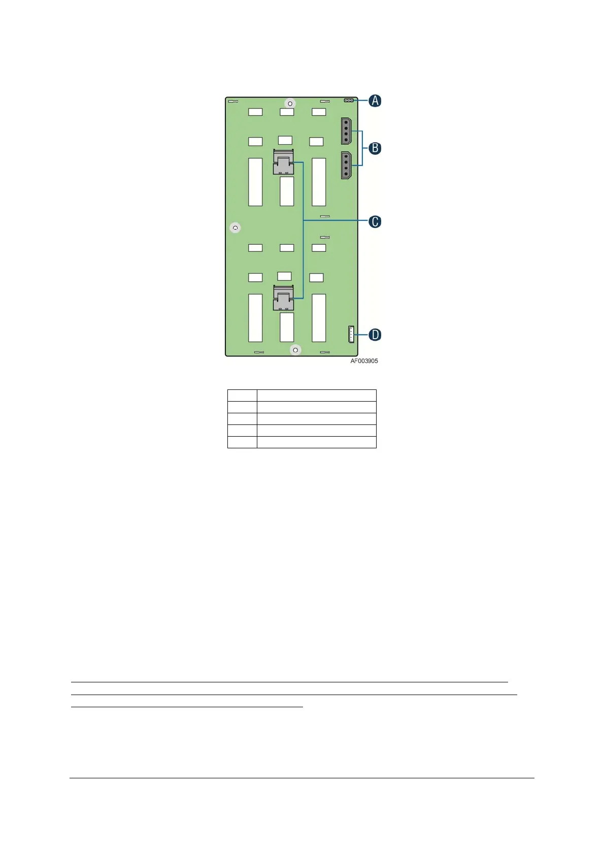
A Reserved
B Power connector
C 4-port mini-SAS connectors
D I2C connector
Figure 44. 2.5” Backplane, Back Side
A – Reserved
B – Power Harness Connector - The backplane includes a 2x2 connector supplying power to
the backplane. Power is routed to the backplane by a power cable harness from the server
board
C – 4-port Mini-SAS Connectors – The backplane includes two or three multi-port mini-SAS
cable connectors, each providing I/O signals for four SAS/SATA hard drives on the backplane.
Cables can be routed from matching connectors on the server board, add-in SAS/SATA RAID
cards, or optionally installed SAS expander cards. Each mini-SAS connector will include a silk-
screen identifying which drives the connector supports; Drives 0-3 and Drives 4-7.
D – I2C Cable Connectors – A cable connector used as a management interface to the server
board.
Note: The two SATA 6G connectors from ACHI (white connectors) on server board are not
recommended to connect to the 8X3.5 backplane. The LED indicators on the front side of the
8X2.5” drive bay will not light up if used as such.

 Loading...


