Intel® Server Board S2600CP Connector/Header Locations and Pin-outs
Intel
®
Server Board S2600CP and Server System P4000CP TPS
Revision 1.1
Intel order number G26942-003
90
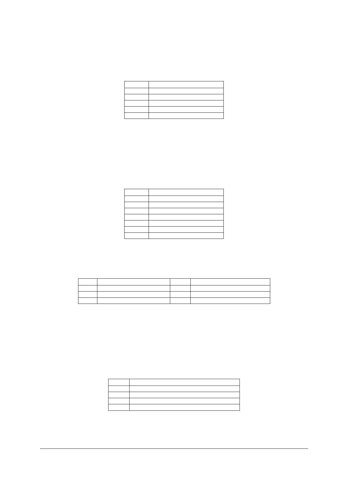
Table 34. SATA SGPIO Connector Pin-out
Pin Signal Name
1 SCLK
2 SLOAD
3 GND
4 SDATAOUT0
5 SDATAOUT1
7.3.4 SAS Connectors
The server board includes eight SAS/SATA connectors. By default, only the connectors labeled
from “SAS_0” to “SAS_3” are enabled and support transfer rates of up to 3Gb/s. The
connectors labeled from “SAS_4” to “SAS_7” are only enabled when an optional Intel
®
RAID
C600 Upgrade Key is installed. The following tables provide the pin-out for each connector.
Table 35. SAS/SATA Connector Pin-out
Pin Signal Name
1 GND
2 SATA_TX_P
3 SATA_TX_N
4 GND
5 SATA_RX_N
6 SATA_RX_P
7 GND
7.3.5 SAS SGPIO Connectors
Table 36. SAS SGPIO Connector Pin-out
Pin Signal Name
Pin
Signal Name
1 CLOCK 2 LOAD
3 GND 4 DATAOUT
5 DATAIN
7.3.6 Intel
®
RAID C600 Upgrade Key Connector
The server board provides one connector to support Intel
®
RAID C600 Upgrade Key. The Intel
®
RAID C600 Upgrade Key is a small PCB board that enables different versions of RAID 5
software stack and/or upgrade from SATA to SAS storage functionality. The pin configuration of
connector is identical and defined in the following table.
Table 37. Intel
®
RAID C600 Upgrade Key Connector Pin-out
Pin Signal Name
1 GND
2 FM_PBG_DYN_SKU_KEY
3 GND
4 FM_SSB_SAS_SATA_RAID_KEY

 Loading...


