Intel
®
Server Board S2600CP and Server System P4000CP TPS Intel
®
Server System P4000CP Power System Options
Revision 1.1
Intel order number G26942-003
155
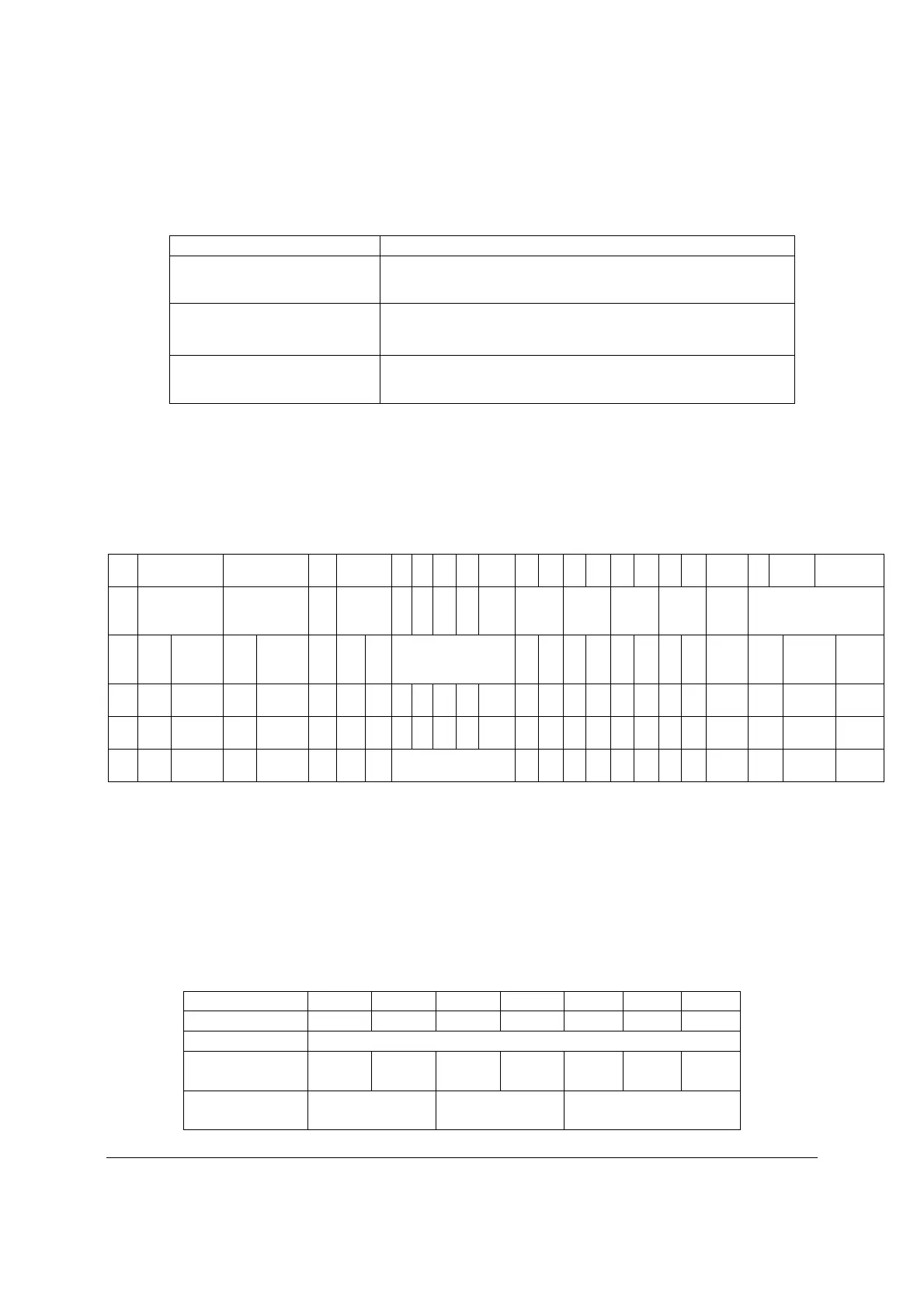
Table 121. Remote Sense Requirements
Characteristic Requirement
+3.3V remote sense input
impedance
200
(measure from +3.3V on P1 2x12 connector to +3.3V sense
on P20 1x5 signal connector)
+3.3V remote sense drop 200mV (remote sense must be able to regulate out 200mV drop
on the +3.3V and return path; from the 2x12 connector to the
remote sense points)
Max remote sense current draw < 5mA
13.4.2.5 12V Rail Distribution
The following table shows the configuration of the 12V rails and what connectors and
components in the system they are powering.
Table 122. 12V Rail Distribution
P2 P3 P12 P1 P8 P9
P1
0
P1
1
P5,6,
7
P1
3
P1
4
P1
5
P1
6
P1
7
P1
8
P1
9
P2
0
2x4 2x4 2x2 2x12
1x
4
1x
4
1x
4
1x
4
(2)
1x5,
1x4 GPU1 GPU2 GPU3 GPU4 OCP
CPU
1
Memory
1
CPU
2
Memory
2
PCI
e
Fan
s
Mis
c
HDD and
peripherals
2x
3 2x4
2x
3 2x4
2x
3 2x4
2x
3 2x4
Total
Curre
nt Min Nominal Max
12V
1
17.8
A 10.5 A
17.8
A 10.5 A
21.7
A
10.0
A
3.0
A 91 A 91 95.5 100
12V
2
6.3
A
12.
5 A
6.3
A
12.
5 A
6.3
A
12.
5 A
6.3
A
12.
5 A 76 A 76 88 100
12V
3 18.0 A 18 A 18 19 20
Note:
+12V current to PCIe slots may be supplied from four different connectors. 12V1 on P2, 12V2 on P3, 12V3 on P1,
and 12V3 on P12. P12 is reserved for board that needs 4 x GPU cards powered. P1 is the main 12V power for
PCIe slot; but additional 12V power can be connected to P2 and/or P3. The motherboard MUST NOT short any
of the 12V rails or connectors together.
13.4.2.6 Hard Drive 12V rail configuration options
The following table shows the hard drive configuration options using the defined power
connectors. In some cases additional converter or ‘Y’ cables are needed.
Table 123. Hard Drive 12V rail configuration options
P8 P9 P10 P11 P5 P6 P7
1x4 1x4 1x4 1x4 1x5 1x5 1x4
18
3 x 2.5" 8xHDD
BP
HDD1
8 x 2.5
HDD2
8 x 2.5 N/a N/a N/a N/a
HDD3
8 x 2.5
2 x 3.5" 4xHDD
BP
HDD1
4x3.5
HDD1
4x3.5 peripheral bay

 Loading...


