Connectors and Jumper Blocks Intel® Server Boards S3200SH/S3210SH TPS
Revision 1.8 89
Intel Order Number: E14960-009
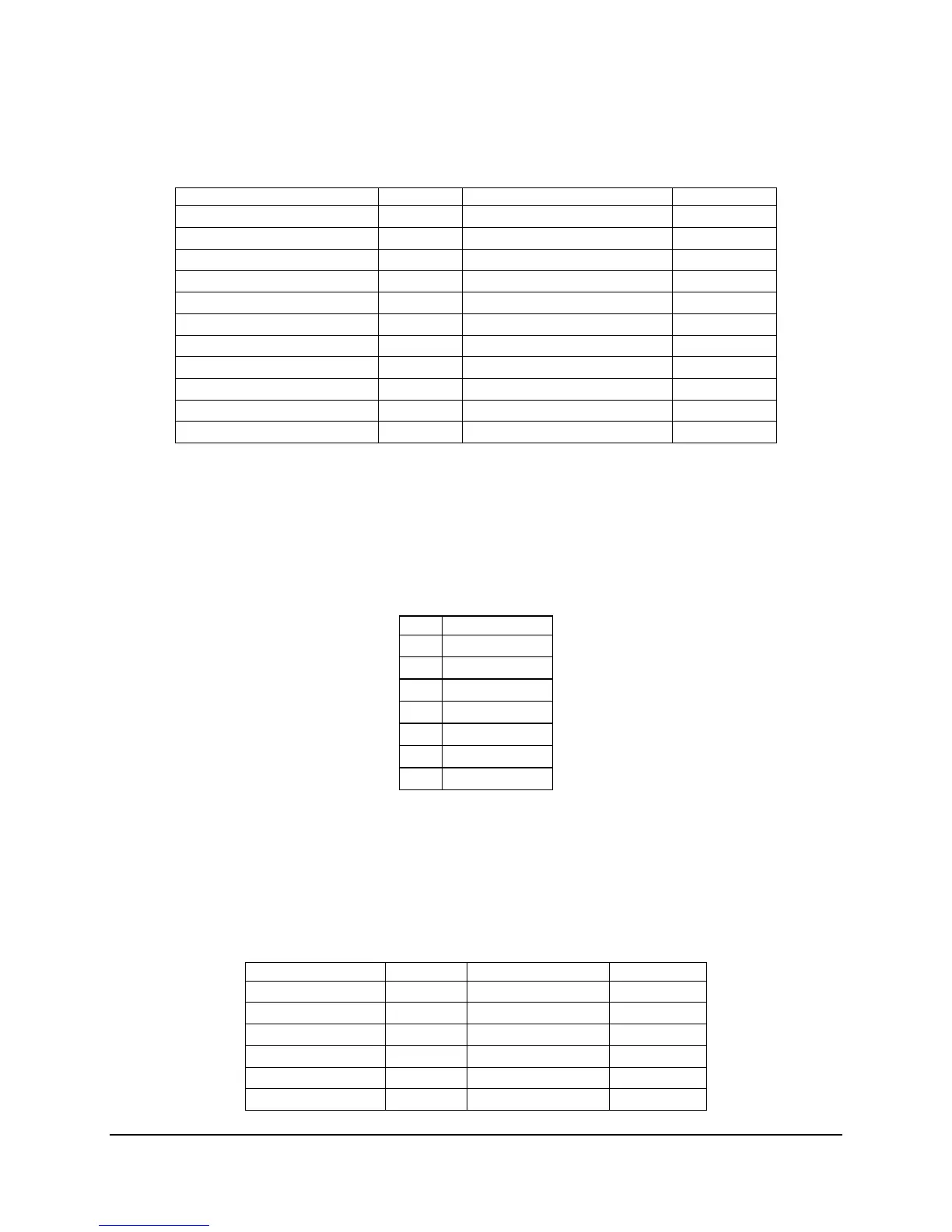
Table 54. NIC1- Intel
®
82566E (10/100/1000) Connector Pin-out (J6B1)
Signal Name Pin Signal Name Pin
P2V5_NIC1 9 P3V3_AUX 20
NIC1_MDI0_DP 10 NIC1_LINK_0_N 21
NIC1_MDI0_DN 11 NIC1_LINK_2_N 22
NIC1_MDI1_DP 12 GND MP1
NIC1_MDI1_DN 13 GND MP2
NIC1_MDI2_DP 14 GND MP3
NIC1_MDI2_DN 15 GND MP4
NIC1_MDI3_DP 16 GND MP5
NIC1_MDI3_DN 17 GND MP6
GND 18 GND MP7
NIC1_LINK_1_N 19 GND MP8
6.5.3 SATA Connectors
Table 55 lists the pin-out for the four SATA connectors.
Table 55. SATA Connector Pin-out (J2K1, J1K1, J1J3, J1H3, J1H2, J1H1)
Pin Signal Name
1 GND
2 SATA0_TX_P
3 SATA0_TX_N
4 GND
5 SATA0_RX_N
6 SATA0_RX_P
7 GND
6.5.4 Floppy Controller Connector
The board provides a standard 34-pin interface to the floppy disk drive controller. The following
table details the pin-out of the 34-pin floppy connector.
Table 56. Legacy 34-pin Floppy Connector Pin-out (J3K1)
Signal Name Pin Signal Name Pin
GND 1 FDDENSEL 2
GND 3 Unused 4
KEY 5 FDDRATE0 6
GND 7 FDINDEX# 8
GND 9 FDMTR0# 10
GND 11 FDR1# 12

 Loading...


