Functional Architecture Intel® Server Boards S3200SH/S3210SH TPS
30 Revision 1.8
Intel Order Number: E14960-009
Table 14. Segment A Arbitration Connections
Baseboard Signals Device
PCI REQ_N5/GNT_N5 Intel
®
82541PI LAN (NIC2)
PCI REQ_N1/GNT_N1 PCI Slot 1 (32-bit/33 MHz)
PCI REQ_N0/GNT_N0 PCI Slot 2 (32-bit/33 MHz)
3.4.1.2 PCI Interface for Video subsystem
The server board graphics subsystem is connected to the Intel
®
ICH9R with a PCI Express* x1
bus.
3.4.2 Interrupt Routing
The board interrupt architecture accommodates both PC-compatible PIC mode and APIC mode
interrupts through the use of integrated I/O APICs in the Intel
®
ICH9R.
3.4.2.1 Legacy Interrupt Routing
For PC-compatible mode, the Intel
®
ICH9R provides two 82C59-compatible interrupt controllers.
The two controllers are cascaded with interrupt levels 8 through 15 entering on level 2 of the
primary interrupt controller (standard PC configuration). A single interrupt signal is presented to
the processor, to which the processor responds for servicing. The Intel
®
ICH9R contains
configuration registers that define which interrupt source logically maps to I/O APIC INTx pins.
The Intel
®
ICH9R handles both PCI and IRQ interrupts. The Intel
®
ICH9R translates these to the
APIC bus. The numbers in Table 15 indicate the Intel
®
ICH9R PCI interrupt input pin to which
the associated device interrupt (INTA, INTB, INTC, INTD, INTE, INTF, INTG, INTH for PCI bus
and PXIRQ0, PXIRQ1, PXIRQ2, PXIRQ3 for PCI-X bus) is connected. The Intel
®
ICH9R I/O
APIC exists on the I/O APIC bus with the processor.
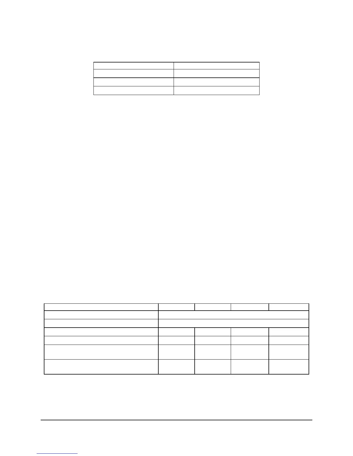
Table 15. PCI AND PCI-X Interrupt Routing/Sharing
Interrupt INT A INT B INT C INT D
Intel
®
82541PI LAN (NIC2) PIRQB
Integrated BMC PIRQC
PCI Slot 1 (PCI 32-bit/33 MHz) PIRQG PIRQF PIRQE PIRQH
PCI Slot 2 (PCI 32-bit/33 MHz) PIRQF PIRQG PIRQH PIRQE
PCI-X Slot 5 (64-bit/133 MHz) (LX board SKU
only)
PXIRQ5 PXIRQ6 PXIRQ7 PXIRQ4
PCI-X Slot 6 (64-bit/133 MHz) (Riser, LX board
SKU only)
PXIRQ0 PXIRQ1 PXIRQ2 PXIRQ3

 Loading...


