Intel® Server Boards S3200SH/S3210SH TPS Connectors and Jumper Blocks
92 Revision 1.8
Intel Order Number: E14960-009
A header on the server board provides an option to support two additional USB connectors. The
following table details the pin-out of the header.
Table 60. Optional USB Connection Header Pin-out (J1G1)
Signal Name Pin Signal Name Pin
NC 1 Key 2
GND 3 GND 4
USB_FRONT1_INDUCTOR_DP 5 USB_FRONT2_INDUCTOR_DP 6
USB_FRONT1_INDUCTOR_DN 7 USB_FRONT2_INDUCTOR_DN 8
USB_FNT_PWR 9 USB_FNT_PWR 10
6.6 Fan Headers
The server board supports five general-purpose fan headers. All fan headers are 4-pin fan
headers (J7J1, J8D1, J4J1, J6B1, and J6J1) and have the same pin-out.
Table 61. Four-pin Fan Headers Pin-out (J4D1, J1K2, J7K1, and J4K1J6B2)
Pin Signal Name Type Description
1 Ground Power GROUND is the power supply ground
2 Fan Power Power Fan Power
3 Fan Tach Out FAN_TACH signal is connected to the Heceta* to monitor the FAN
speed.
4 PWM Control Pulse Width Modulation – Fan Speed Control signal
6.7 Miscellaneous Headers and Connectors
6.7.1 Back Panel I/O Connectors
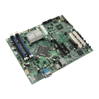
Figure 35. Intel
®
Server Board S3210SHLX / S3210SHLC / S3200SHL Back Panel I/O Connectors
 Loading...

