Intel® Server Boards S3200SH/S3210SH TPS Functional Architecture
Revision 1.8 29
Intel Order Number: E14960-009
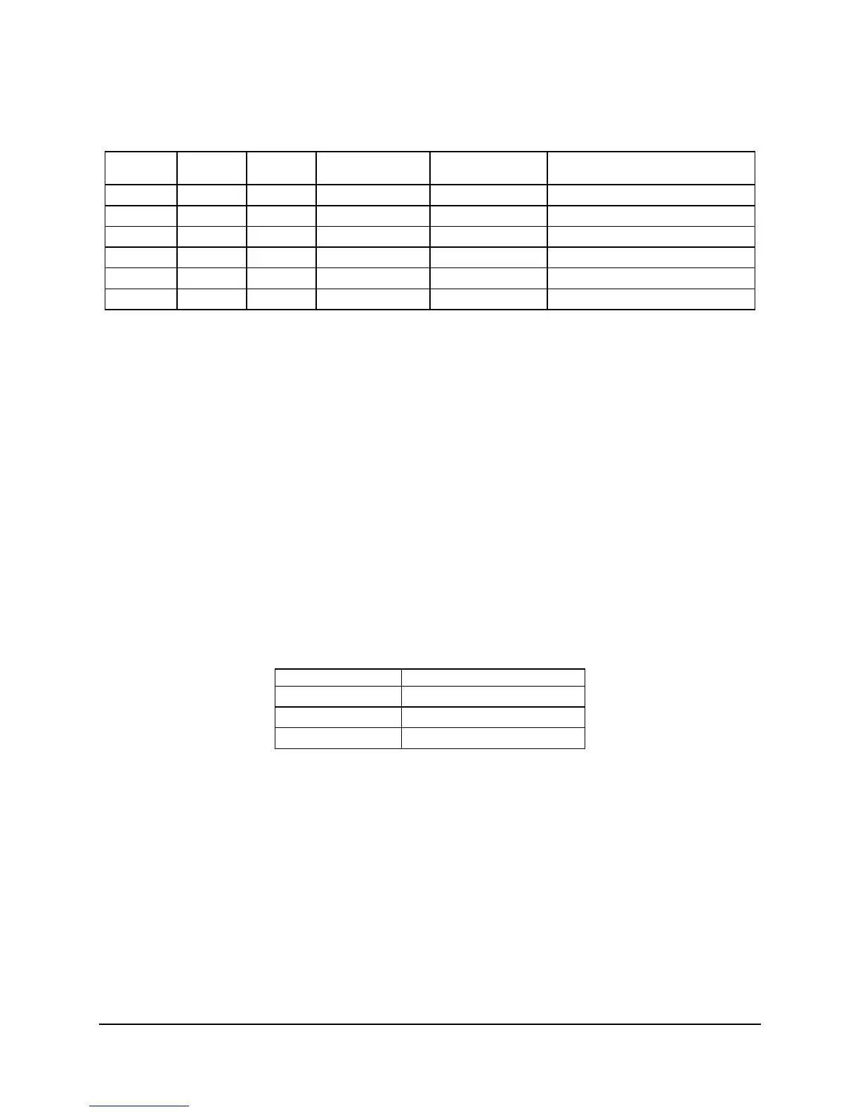
Table 12. PCI Bus Segment Characteristics
PCI Bus
Segment
Voltage Width Speed Type PCI I/O Card Slots
A 3.3V 32 bits 33 MHz PCI 32 Slot 1, Slot 2, NIC 2, video
B 3.3V 1 lane 2.5 GHz x1 PCI Express* Slot 3, X4 physical connector
C 3.3V 1 lane 2.5 GHz x1 PCI Express* NIC 1
D 3.3V 4 lane 2.5 GHz x4 PCI Express* Slot 4, PXH, X8 physical connector
E 3.3V 64 bits 66/100/133 MHz PCI-64 Slot 5, Slot 6 through riser card
F 3.3V 8 lanes 2.5 GHz x8 PCI Express* Slot 6, X8 physical connector
3.4.1.1 P32-A: 32-bit, 33-MHz PCI Sub-system
The Intel
®
ICH9R provides a Legacy 32-bit PCI sub-system and acts as the central resource on
this PCI interface. P32-A supports the following embedded devices and connectors:
One Intel
®
82541PI Fast Ethernet Controller
Two slots capable of supporting full length PCI add-in cards operating at 33 MHz
3.4.1.1.1 Device IDs (IDSEL)
Each device under the PCI hub bridge has its IDSEL signal connected to one bit of AD (31:16),
which acts as a chip select on the PCI bus segment in configuration cycles. This determines a
unique PCI device ID value for use in configuration cycles. The following table shows the bit to
which each IDSEL signal is attached for segment A devices and the corresponding device
description.
Table 13. Segment A Configuration IDs
IDSEL Value Device
21 Intel
®
82541PI LAN (NIC2)
17 PCI Slot 1(32b/33MHz)
16 PCI slot 2(32b/33MHz)
3.4.1.1.2 Segment A Arbitration
PCI segment A supports two PCI devices: the Intel
®
ICH9R and one PCI bus master (NIC). All
PCI masters must arbitrate for PCI access using resources supplied by the Intel
®
ICH9R. The
host bridge PCI interface (ICH9R) arbitration lines REQx* and GNTx* are a special case in that
they are internal to the host bridge. Table 14 defines the arbitration connections.

 Loading...


