Intel® Server Boards S3200SH/S3210SH TPS Connectors and Jumper Blocks
86 Revision 1.8
Intel Order Number: E14960-009
6. Connectors and Jumper Blocks
6.1 Power Connectors
6.1.1 Main Power Connector
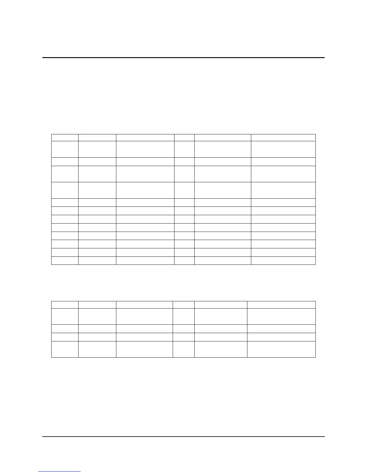
The following table defines the pin-out of the main power connector.
Table 48. Power Connector Pin-out (J4G1)
Pin Signal 18 AWG Color Pin Signal 18 AWG Color
1* +3.3VDC
3.3V RS
Orange
Orange (24AWG)
13 +3.3VDC Orange
2 +3.3VDC Orange 14 -12VDC Blue
3* COM
COM RS
Black
Black (24AWG)
15 COM Black
4* +5VDC
5V RS
Red
Red (24AWG)
16 PSON# Green
5 COM Black 17 COM Black
6 +5VDC Red 18 COM Black
7 COM Black 19 COM Black
8 PWR OK Gray 20 Reserved N.C.
9 5 VSB Purple 21 +5VDC Red
10 +12V3 Yellow 22 +5VDC Red
11 +12V3 Yellow 23 +5VDC Red
12 +3.3VDC Orange 24 COM Black
Table 49. Auxiliary CPU Power Connector Pin-out (J9B2)
Pin Signal 18 AWG color Pin Signal 18 AWG Color
1 COM Black 5* +12V1
12V1 RS
White
Yellow (24AWG)
2 COM Black 6 +12V1 White
3 COM Black 7 +12V2 Brown
4 COM Black 8* +12V2
12V2 RS
Brown
Yellow (24AWG)

 Loading...


