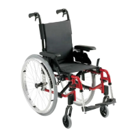
4.2.3.2 ACT 4 actuator module
Connections
1) ACI*
2) Bus cable (ACT or power module)
3) Bus cable (ACT or power module)
4) Actuator - Channel 4
5) Actuator - Channel 3
6) Actuator - Channel 2
7) Actuator - Channel 1
Rubber stoppers for free slots
1) Order number: 1555701
2) & 3) Order number: 1552876
4) to 7) Order number: 1555700
* The ACI connection is used for actuator limitation or speed reduction.
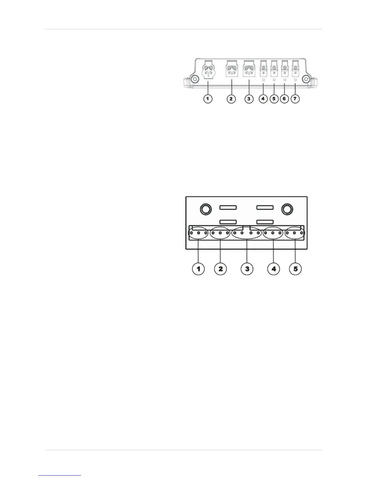
4.2.4 Lighting PCB
Connections
1) Driving light & l.h. indicator 1
2) Driving light & l.h. indicator 2
3) Power module
4) Driving light & r.h. indicator 1
5) Driving light & r.h. indicator 2
The lighting PCB connections are printed directly on the circuit board.