iPECS-MG
Hardware Description and Installation Manual Issue 1.1
23
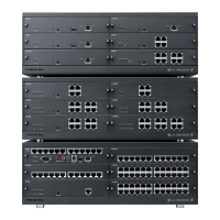
4.5 Expansion KSU Installation
The Expansion KSU is installed on top of the Basic KSU. Fasteners are installed on each side
of the KSUs to maintain a stable mechanical connection. The Expansion cable is installed to
connect the KSU backplane signaling and media (voice) paths. Use the following instructions
and Figure below to install.
1. Remove the Expansion Cable Cover Plates on the top of the BKSU and bottom of the
EKSU. Remove the two screws holding the Cover plate and remove the Cover plate.
2. Install the Rack Mounting brackets on the EKSU with the screws provided.
3. For Wall Mounting
Place the EKSU on top of the BKSU, making sure to align the feet of the EKSU with
the cavities in the lower KSU.
For 19” Rack mounting,
Insert screws and washers through the Rack Mounting bracket on each side of the
cabinet.
If required, thread screws into nuts, or directly into threaded holes in the 19” rack and
tighten screws securely.
4. Install the Fasteners on each side of the cabinets using the screws provided with the
EKSU.
5. Install the Expansion cable between the two cabinets. Attach one connector to the
C8 mating connector in the lower KSU and the other end to C9 in the upper KSU. It
may be necessary to remove the blank Slot cover plates from the front of the KSUs.
CAUTION
Be careful not to bend the pins of Expansion Cable connectors.
If the site requires a second EKSU, install and connect the second EKSU to the first EKSU as
described above.