iPECS-MG
Hardware Description and Installation Manual Issue 1.1
89
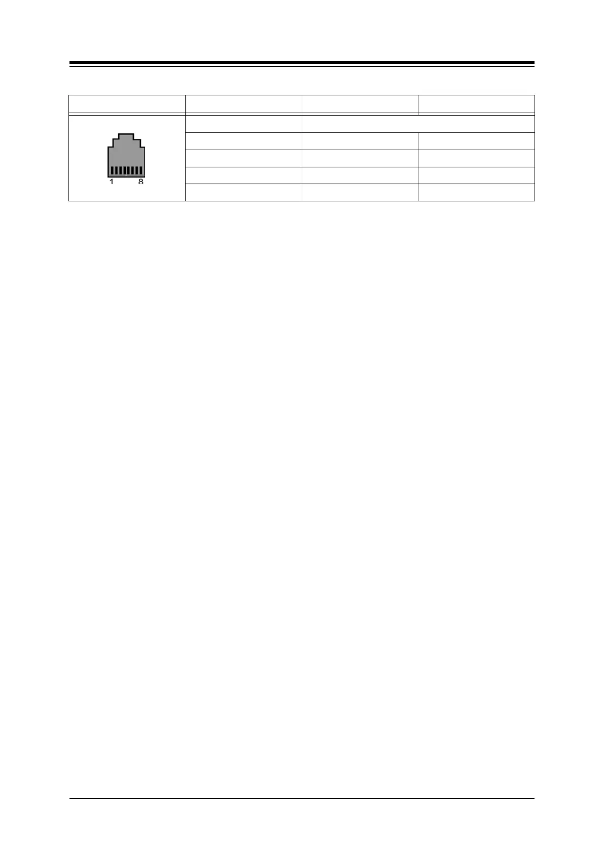
Table 6.1.2.3-1 IP Phone Pin-out Chart
CONNECTOR PIN SIGNAL NAME FUNCTION
RJ45 4,5,7,8 Not used
1 TX+ Transmit Data
2 TX- Transmit Data
3 RX- Receive Data
6 RX+ Receive Data
6.1.3 LDP Door Phone Box
The iPECS-MG supports the LDP DPB, digital Door Phone Box. The Door Phone Box can
place a call to assigned stations and a station can answer the Door Phone Box call. If
configured, the station user can activate a door-lock release mechanism to allow entry.
6.1.3.1 Door Phone Box Installation
The Door Phone Box can be wall mounted in a protected environment; the DPB is not intended
for exterior application. To wall mount the LDP-DPB,
Locate the mounting position for the Door Phone Box,
Mark position for two (2) screws
Drill holes for two (2) plastic anchors
Insert screws and tighten leaving about ¼ inch exposed.
Align the screw holes in the back of the LDP-DPB with the screws and slide down to
lock in place. It may be necessary to remove the box and loosen or tighten the
screws for a secure fit.
6.1.3.2 Door Phone Box Wiring
The Door Phone Box is wired using screw terminals in the box. The terminals are wired to any
available DKT port except for the first DKT port.
Referring to Figure 6.1.3.2-1 and the pin-out chart below,
Loosen the screw holding the Door Phone Box cover.
Loosen the two (2) screw terminals.
Using a UTP cable terminated on one end with an RJ11, strip approximately ¼ inch
of insulation from the center pair at the un-terminated end of the wire.
Insert the DKT Tip in one terminal and the DKT Ring.
Tighten the screws to connect and securely fasten the wires.
Plug the terminated end of the wire into a standard wall outlet with an RJ11.
Wire the wall outlet 1st pair to the DTIB or DSIU termination point using UTP cable.