iPECS-MG
Hardware Description and Installation Manual Issue 1.1
72
5.4.5.2 DECT Installation
For detailed instructions on Site Planning for Base Stations, Cell-coverage Region Survey,
RSSI Monitoring, and Base Station Installation, refer to the DECT Installation Guide for iPECS-
MG.
5.4.5.3 WTIB Installation
Prior to installation, assure the Dipswitch settings are in the default position, section 5.4.5.1.
The WTIB can be installed in any universal slot of any KSU; the 1st slot of the BKSU is for the
MPB only. Note when installing more than one WTIB, all WTIBs should be installed in the same
KSU.
Assure Power is OFF.
Slide the WTIB in the guide rails of the desired slot.
Tighten thumbscrews to hold the board firmly in place.
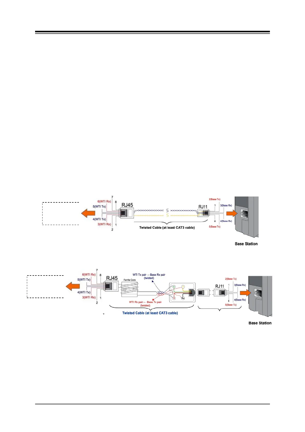
5.4.5.4 Ferrite Core Installation
A ferrite core is provided in the packaging of the System DECT Base Station. When properly
installed, the ferrite core reduces Electro-Magnetic Interference from the Base Station. The
Ferrite core should be installed on each cable that is connected to the WTIB as close to the
WTIB connector as possible. Using RJ45 terminate CAT3 cable, wrap the Ferrite core as
shown in Figure 5.4.5.4-1.
Figure 5.4.5.4-1 WTIB Ferrite Code and Base Station
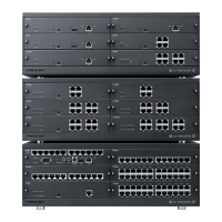
WTIB4 &
WTIB4 &
CAT5 cable provided by Ericsson-LG,
Twisted Cable (At least CAT3 cable)