iPECS-MG
Hardware Description and Installation Manual Issue 1.1
14
3. INSTALLATION OVERVIEW
3.1 General Installation Procedure
The basic steps to install an iPECS-MG are:
1. Locate the area for installing the system
2. Verify all equipment for the installation is on-site
3. Install the Basic and Expansion cabinets
4. Install the various boards in the cabinets
5. Wire the boards to the appropriate termination points
6. Wire and connect terminals
7. Initial power-up to default the database
8. Configure the system, see iPECS Feature and Admin Manuals
9. Verify the installation.
3.2 Types of Connectors
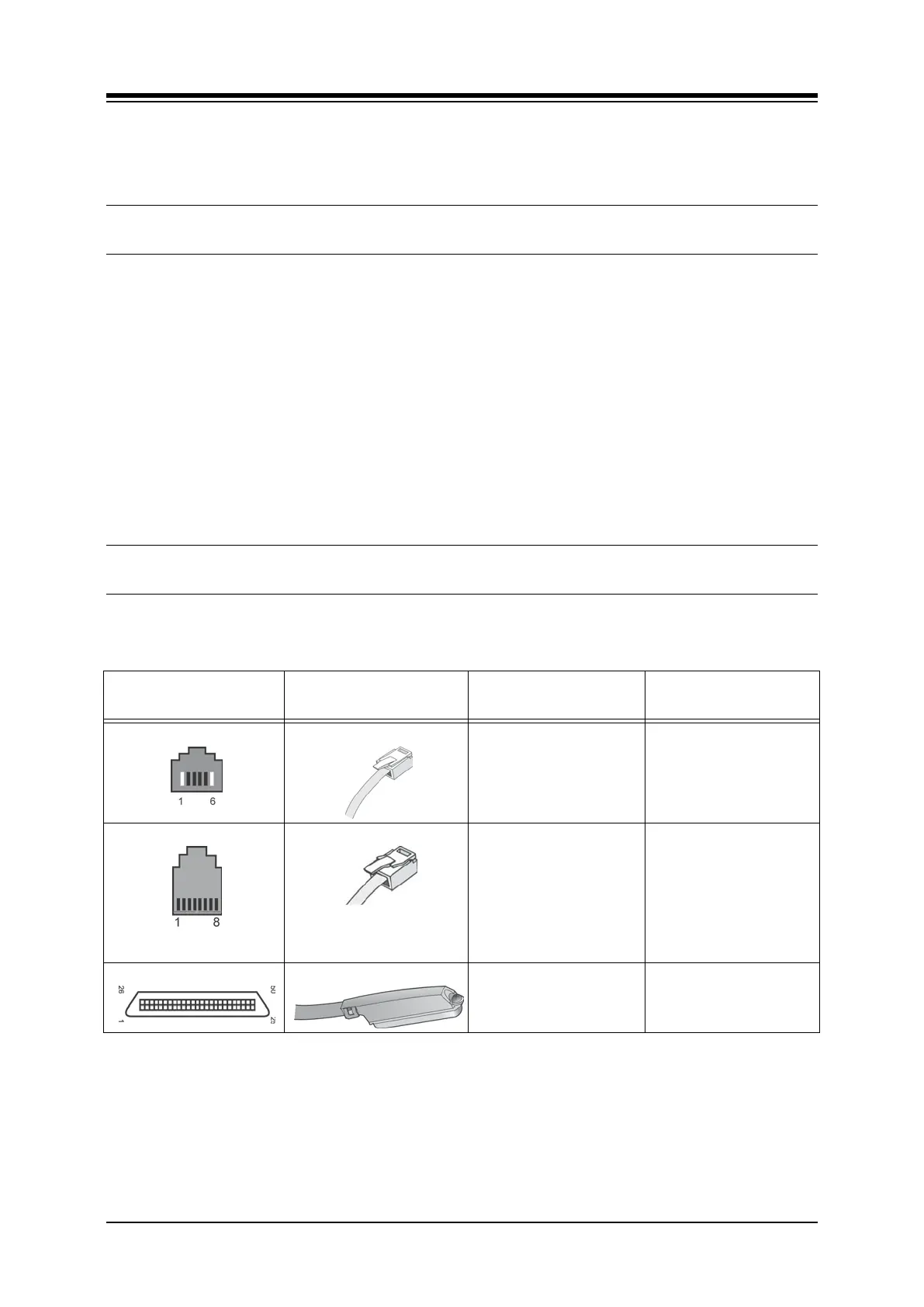
The following chart displays the various types of connectors employed with the iPECS-MG and
the various boards.
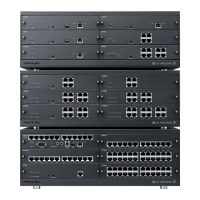
iPECS-MG
CONNECTOR TYPE
MATING-CONNECTOR BOARD PURPOSE
RJ11
MPB Relay and Alarm Port
RJ45
MPB, VOIB8, VOIB24,
VMIB, AAIB, WTIB4,
WTIB8.
DSIU, DTIB12, DTIB24,
SLIB12,SLIB24
LCOB4, LCOB8, LCOB12
PRIB, BRIB4, BRIB8
LAN Port
Telephony Ports
DKT Ports
SLT Ports
LCO Ports
ISDN channels
RJ21 (Female)
(Male)
DTIB12C, DTIB24C
SLIB12C, SLIB24C
DKT Ports
SLT Ports