iPECS-MG
Hardware Description and Installation Manual Issue 1.1
37
5.2.7 RS-232 Monitor Wiring
The RS-232 female connector, which is a DCE (Data Communication Equipment), is used for
various output functions (SMDR, Traffic Reports, etc.) and can be used to access the System
database and maintenance functions through connection to a local PC.
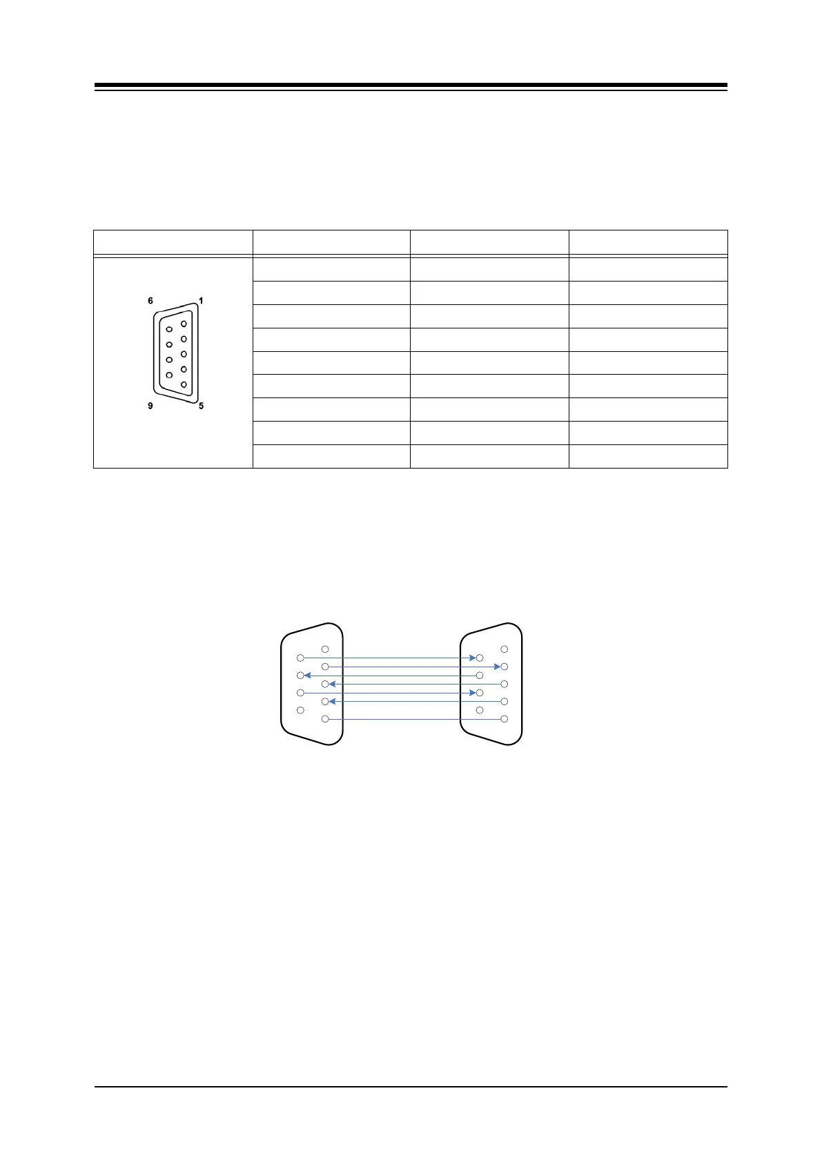
Table 5.2.7-1 RS-232 Monitor Connector
CONNECTOR PIN SIGNAL FUNCTION
RS-232C
1 Not used
2 TD Transmitted Data
3 RD Received Data
4 DSR Data Set Ready
5 SG Signal Ground
6 DTR Data Terminal Ready
7 CTS Clear to Send
8 RTS Request to Send
9 Not used
NOTE
The RS-232C port on the MPB does not support hardware flow control.
Referring to the pin-out chart above and the wiring diagram below,
wire the RS-232 port to an appropriate DTE (Data Terminal Equipment),
tag or number wiring for maintenance
1
2
3
4
5
6
7
8
9
1
2
3
4
5
6
7
8
9
DTR
TD
CTS
RD
RTS
DSR
SG
DSR
RD
RTS
TD
CTS
DTR
SG
LIK MODULE
DB-9 RS-232
TERMINATIONS
TYPICAL TERMINAL
DB-9 RS-232
TERMINATIONS
LIP-8000
iPECS-MG DB-