iPECS-MG
Hardware Description and Installation Manual Issue 1.1
63
5.4.3.1 LED Functions
Table 5.4.5.1-1 LED Indication
LED FUNCTIONS REMARK
LD1 IN USE
ON: Channel in use,
OFF: All channels Idle
LD2 ACT, Activation or Normal Operating Blink (Blue Color)
5.4.3.2 DTIB Installation
The DTIB has no switches or connectors that are field useable. The DTIB can be installed in
any universal slot of any KSU; the 1st slot of the BKSU is for the MPB only. Note a maximum of
four (4) DTIB24/SLIB24s can be installed in a KSU.
Assure Power is OFF
Slide the DTIB in the guide rails of the desired slot.
Tighten thumbscrews to hold the board firmly in place.
5.4.3.3 DTIB Wiring
A separate RJ45 is provided for each DKT port on the DTIB (12 or 24 connectors). DKT ports
terminate on the center pair of the RJ45 connectors.
Referring to the pin-out chart below,
Wire pins 4 and 5 of the RJ45 connector to the DKT termination point using UTP
cable. The maximum total wire length is 500M/1.6Kft of 22 AWG or 330M/1Kft of 24
AWG wire. For information on wiring the Digital Key Telephone, refer to section
6.1.2.1
Tag or number wiring for maintenance.
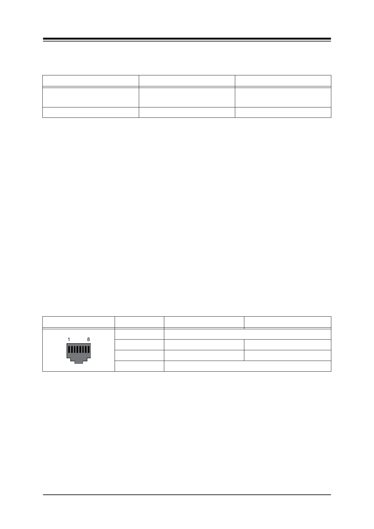
Table 5.4.5.3-1 DTIB RJ45 Pin-Out Chart
CONNECTOR PIN SIGNAL NAME FUNCTION
RJ45 1,2,3 Not used
4 DKT_RX Receive Data
5 DKT_TX Transmit Data
6,7,8 Not used