iPECS-MG
Hardware Description and Installation Manual Issue 1.1
41
5.3.1.3 LCOB Wiring
The CO Line Tip and Ring terminations are located on the center pair of each RJ45 connector.
A separate RJ45 is provided for each analog CO Line supported by the LCOB (4, 8, or 12).
Referring to the pin-out chart below,
Wire the CO Tip and Ring pins to the PSTN CO Line termination point using UTP
cable.
Tag or number wiring for maintenance.
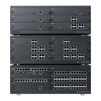
Table 5.3.1.3-1 LCOB Ports
CONNECTOR PIN SIGNAL NAME
RJ45 1,2,3 Not used
4,5 CO-T, CO-R
6,7,8 Not used
The first LCOB CO Line port supports PFT (Power Fail Transfer), when power is lost the CO
Line is connected to an SLT port of an SLIB. To support PFT, referring to the pin-out chart
below,
wire pins 1 and 2 of the 1st LCOB port RJ45 to the appropriate SLIB port. For SLIB
wiring, refer to section 5.4.1 and 5.4.2.
tag or number wiring for maintenance
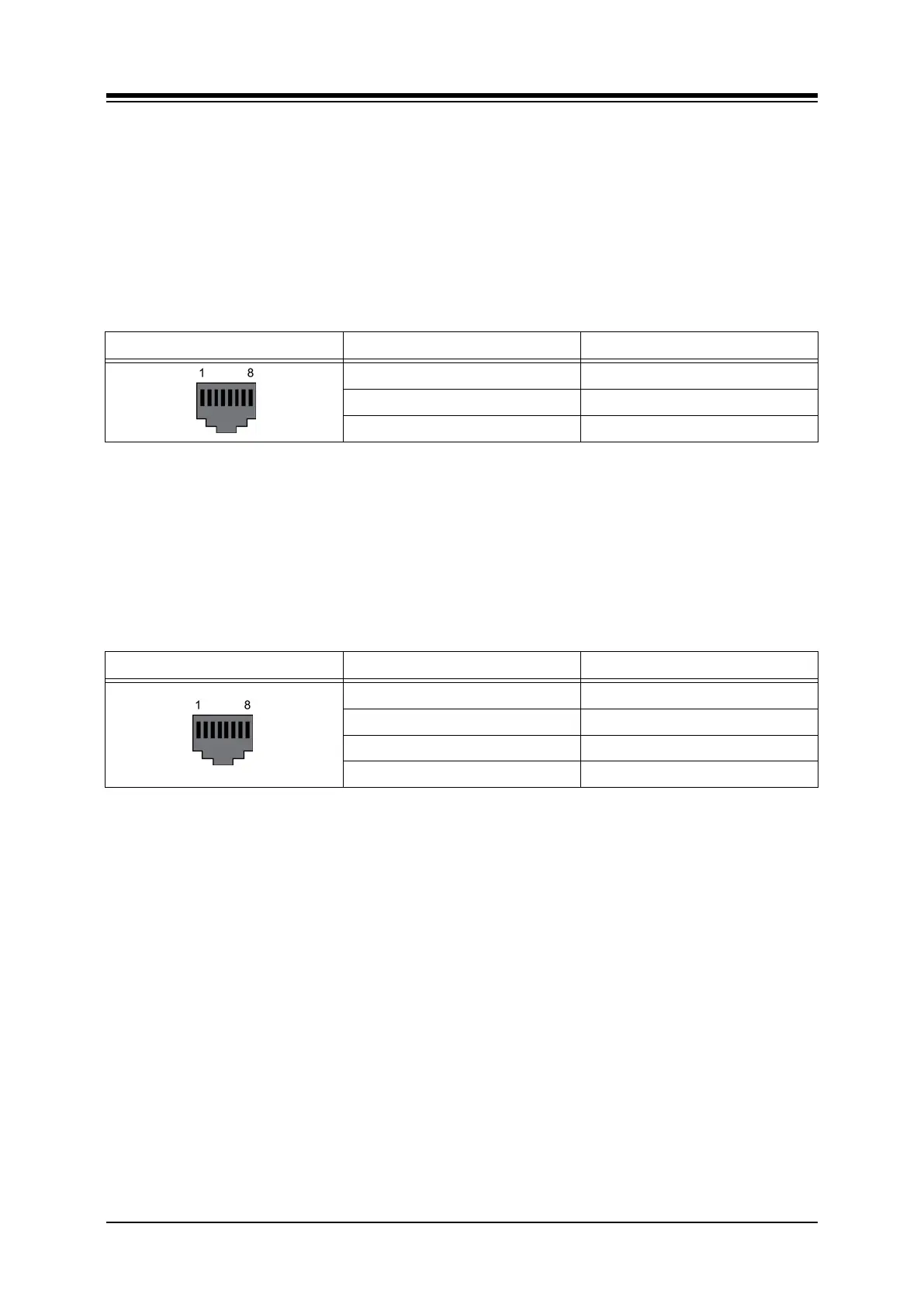
Table 5.3.1.3-2 PFT Port 1
st
Port
CONNECTOR PIN SIGNAL NAME
RJ45 1,2 PFT-T, PFT-R
3 Not used
4,5 CO-T, CO-R
6,7,8 Not used