iPECS-MG
Hardware Description and Installation Manual Issue 1.1
79
Table 5.5.2.1-2 LED Indication
LED FUNCTION REMARK
LD1 VOIB Task Active (CMD/Event Processing) Blink (Blue Color)
LD2 Trace Task Active (Line Monitor) Blink (Blue Color)
LD3 Transcoding
On: Transcoding in use
Off – Transcoding not in use
LD4 Active VOIP call (Channel in use)
On: Channel in use,
OFF: All channels Idle
RJ45-LD1
(Green/Orange)
Data Link
On Link - established
Blink – Data transfer
RJ45-LD2
(Yellow)
Port speed
On – 100 Mbps
Off – 10 Mbps
5.5.2.2 VOIB Installation
The VOIB Dip switches should be set to the OFF position before installation. To install the
VOIB,
Assure Power is OFF
Slide the VOIB in the guide rails of the desired slot.
Tighten thumbscrews to hold the board firmly in place.
5.5.2.3 VOIB Wiring
The VOIB is connected to the LAN through the RJ45 connector on the front panel. The
connector is terminated as a standard EIA 568B MDI (Media Dependent Interface) port.
Referring to the pin-out chart below,
Using UTP cable, wire each VOIB TX and RX pairs to the termination point of an
Ethernet switch port RX and TX pairs, respectively.
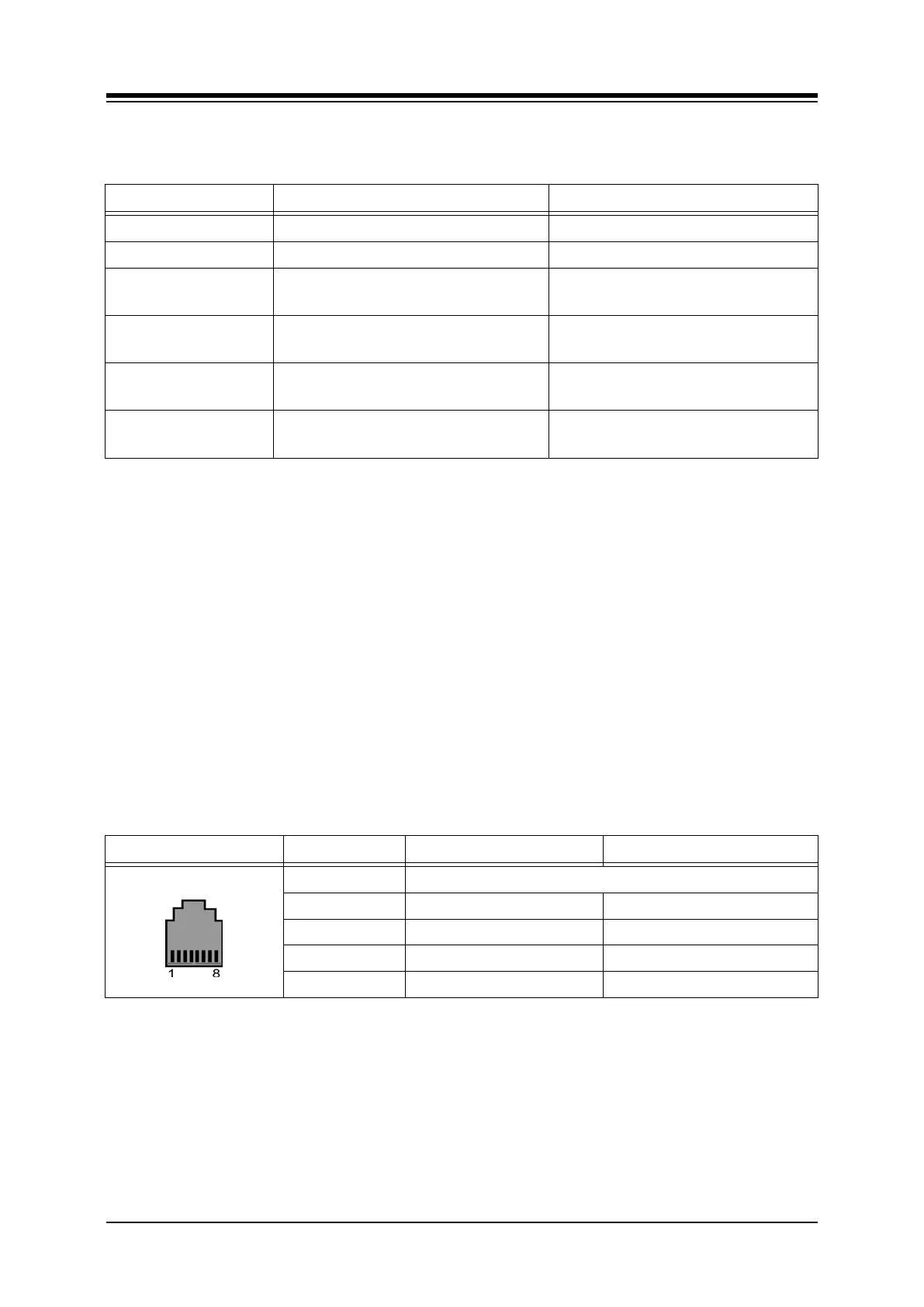
Table 5.5.2.3-1 VOIB LAN PORT
CONNECTOR PIN SIGNAL NAME FUNCTION
RJ45 4,5,7,8 Not used
1 TX+ Transmit Data
2 TX- Transmit Data
3 RX- Receive Data
6 RX+ Receive Data
5.5.2.4 Serial Port
The VOIB include an Audio jack connected to a Serial port. The serial port is used for
diagnostic purposes. For wiring information, refer to section 5.6.