iPECS-MG
Hardware Description and Installation Manual Issue 1.1
88
6.1.2.2 SLT wiring
SLTs are wired to the center pair of the RJ11, typically on the bottom or back of the SLT. The
wall outlet should be connected back to an appropriate SLIB or DSIU SLT port.
Referring to the pin-out chart below and Figure 6.1.1-1,
1. Wire the center pair of the wall outlet to the SLIB or DSIU termination point using UTP
cable.
2. Using the line cord provided with the SLT, connect the SLT to the wall outlet.
Table 6.1.2.2-1 Standard SLT Pin-out Chart
Line Cord CONNECTOR PIN SIGNAL NAME
RJ11 1,2 Not used
3 Ring
4 Tip
5,6 Not used
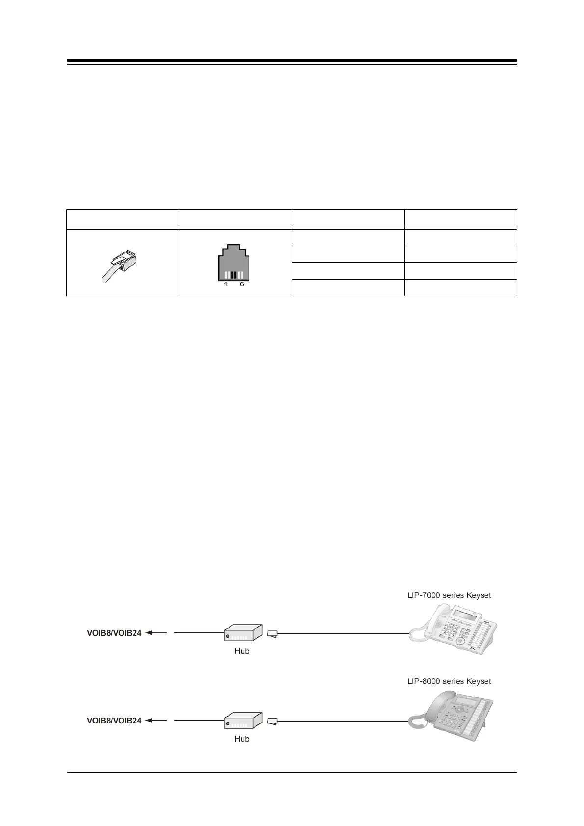
6.1.2.3 LIP-7000 & LIP-8000 & 8000E Series Keyset Wiring
The iPECS-MG supports the LIP-7000 and 8000 series IP Phones. The LIP-7008D and the
LIP-8004D have a single LAN port that is wired to an Ethernet switch port. All other LIP-7000
and 8000 & 8000E series phones shown here have two (2) Ethernet ports, a LAN port and a
PC port. The LAN port is connected to an Ethernet switch port and the PC port is connected to
the LAN port of a PC. The LIP phones are wired to any 10/100 Base-T Ethernet switch port
with access to a VOIB channel. The LIP phones can be powered from a POE compatible
Ethernet switch port or using the AC/DC Adaptor-K.
Referring to Figure 6.1.2.3-1 and the IP Phone pin-out chart below,
Wire the RX and TX pins from the RJ45 Wall outlet, or equal, for the IP Phone to the
appropriate Ethernet switch termination point using Cat 5 UTP cable. The maximum
wire length between the IP Phone and the Ethernet switch port is 100m or 328 feet.
Use the RJ45 terminated cable provided with the phone to connect the IP Phone to
the Wall outlet.
Connect the PC port to a PC LAN port using a CAT 5 cable terminated on each end
with an RJ45 connector.
If not using a POE switch port, connect the DC connector of an AC Adaptor-K to the
DC input on the bottom of the IP Phone and plug the AC plug of the AC adaptor in
to a 100-240 VAC outlet.
Figure 6.1.2.3-1 LIP Phone Connection