iPECS-MG
Hardware Description and Installation Manual Issue 1.1
50
Assure Power is OFF
Slide the PRIB in the guide rails of the desired slot.
Tighten thumbscrews to hold the board firmly in place.
5.3.3.3 E1-PRIB Wiring
The E1-PRIB Transmit and Receive pairs are terminated in the PRI/E1 RJ45 connector. A
single RJ45 is provided for the digital line interface.
Before wiring the PRIB, the Ferrite core provided with the E1-PRIB must be installed to reduce
EMI (Electro-Magnetic Interference). To install the Ferrite core,
Open the core,
Insert and loop the RJ45 terminated cable for the E1-PRIB through the core as
shown in Figure 5.3.3-1.
Close the Ferrite core over the cable.
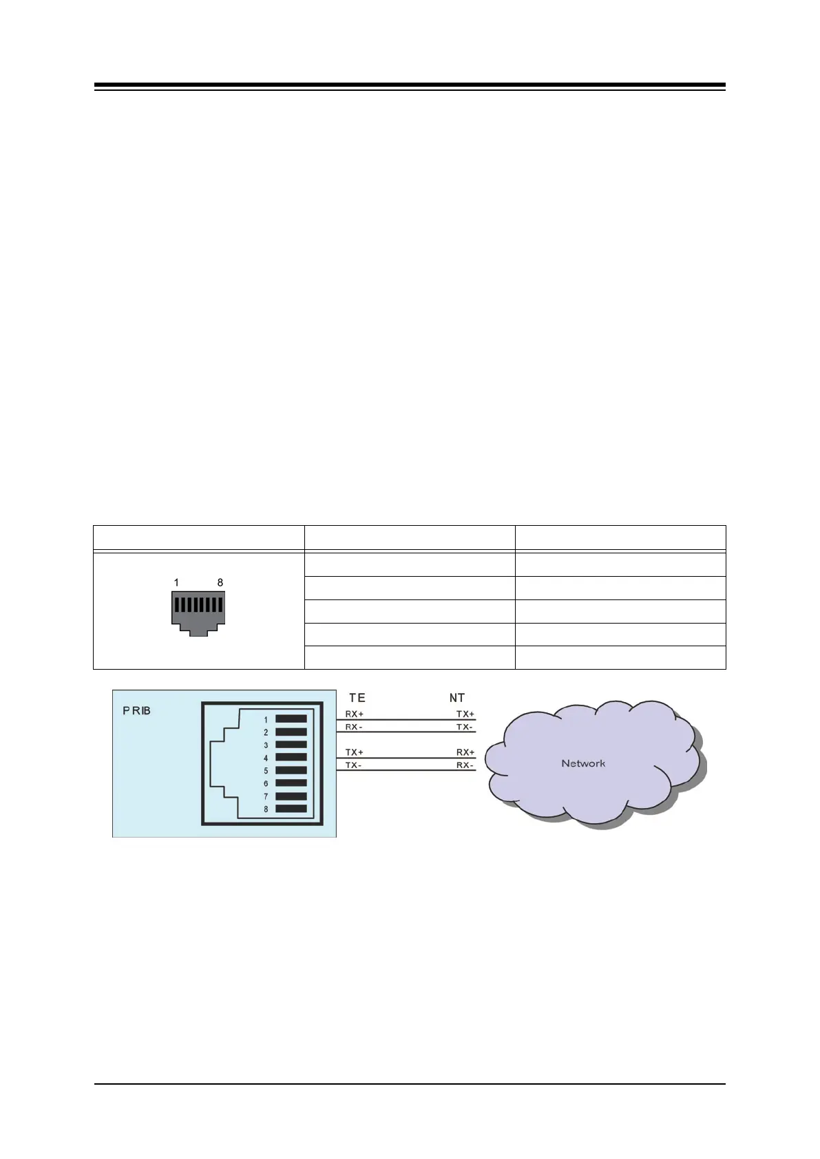
Referring to the pin-out chart and Figure 5.3.3.3-1 E1-PRIB Connector Wiring Diagram below,
Wire the TX and RX pins of the RJ45 connector to the digital line termination point
using UTP cable.
Tag or number wiring for maintenance.
Table 5.3.3.3-1 PRI Port
CONNECTOR PIN SIGNAL
RJ45 1 RX+
2 RX-
4 TX+
5 TX-
3,6,7,8 Not used
Figure 5.3.3.3-1 E1-PRIB Connector Wiring Diagram
5.3.3.4 Serial Port
The PRIB includes an Audio jack connected to a Serial port. The serial port is used for
diagnostic purposes. For wiring information, refer to section 5.6.