iPECS-MG
Hardware Description and Installation Manual Issue 1.1
66
Table 5.4.6.1-1 LED Indication
LED FUNCTION REMARK
LD11 The status of 11
th
port or 23
rd
port
ON (Blue) : 11
th
port Use
ON (Yellow Green) : 23
rd
port Use
ON (Blush white) : 11
th
and 23
rd
port Use
OFF: Idle
LD12 The status of 12
th
port or 24
th
port
ON (Blue) : 12
th
port Use
ON (Yellow Green) : 24
th
port Use
ON (Blush white) : 12
th
and 24
th
port Use
OFF: Idle
LD13 ACT, Activation or Normal Operating Blink (Blue Color)
LD14 In use
ON: Ch. Use,
OFF: All channels Idle
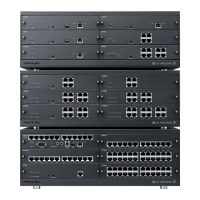
5.4.4.2 DTIBC Installation
The DTIBC has no switches or connectors that are field useable. The DTIBC can be installed in
any universal slot of any KSU; the 1st slot of the BKSU is for the MPB only. Note a maximum of
four (4) DTIB24C/SLIB24s can be installed in a KSU.
Assure Power is OFF
Slide the DTIBC in the guide rails of the desired slot.
Tighten thumbscrews to hold the board firmly in place.
5.4.4.3 DTIBC Wiring
Each DKT port is terminated to a pair in the RJ21 connector. DKT 1 is terminated at pair 1,
DKT 2 is terminated on pair 2, etc. to the number of ports (12 or 24) on the DTIBC.
Referring to the pin-out chart below,
Wire each DKT pair on the RJ21 connector to the DKT termination point using UTP
cable. The maximum total wire length is 500M/1.6Kft of 22 AWG or 330M/1Kft of 24
AWG wire. For information on wiring the DKT, refer to section 6.1.2.1.
Tag or number wiring for maintenance.