82
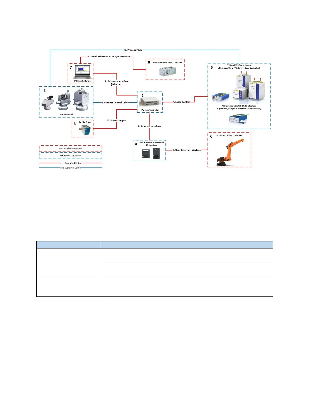
Figure 10-2 Robotic Scanning System Example Diagram
Be sure to check the water cooling requirements for the giving application.
10.4.1.2 Hardware
In addition to the outlined items in Table 10-1, Table 10-2 outlines the required number of Robot or PLC
I/O given the proper External Control Interface.
Table 10-2 Required Hardware - Point and Shoot Processing
24V Interface: 12 outputs are required
Extended IO Interface: 12 outputs are required, 19 can be used
24V Interface: 3 inputs are required, 4 inputs can be used
Extended IO Interface: 3 inputs are required, 16 can be used
24V Interface or
Extended IO Interface
Interface between robot signals and scanner signals. Cables between the
robot I/O, external interface board, and the Scan Controller are supplied
by the customer.
10.4.1.3 Point and Shoot Programming
Please refer to the IPGScan Software User Guide for additional information on scanner programming
and timing diagrams.