Chapter 6 MECHANICAL ADJUSTMENT
6.6 THERMAL HEAD POSITION
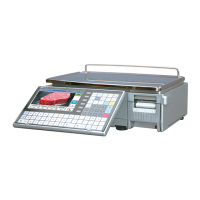
1.
Pull out the cassette unit from the main
body.
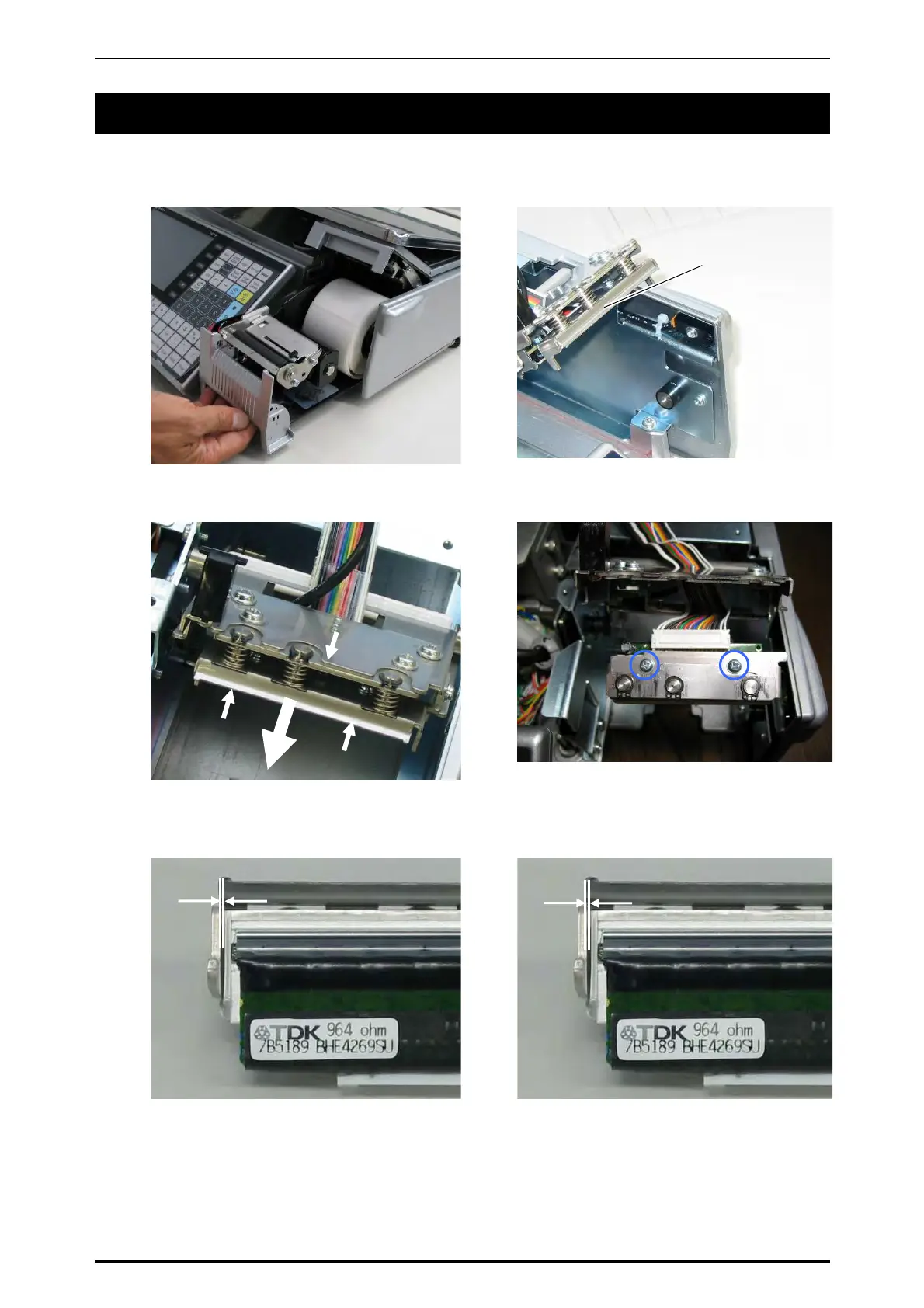
2.
The following photo shows the position of
the thermal head unit.
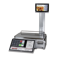
3.
Squeeze the springs by holding up the
head bracket and pull out the thermal head
unit.
4.
Loosen the two screws to adjust the gap
between the bracket and the left end of the
thermal head.
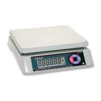
5-1
When using the backing paper of up to
62mm width, adjust the gap between the
bracket and the left end of the thermal
head to be 2mm ±0.5mm.
5-
When using the backing paper of 64mm
width, adjust the gap between the bracket
and the left end of the thermal head to be
3mm ±0.5mm.
Thermal head unit
3mm
2mm
6-6 UNI-7 Service Manual