Chapter 5 MACHINE DISASSEMBLY
5.1.4 OPERATION PANEL
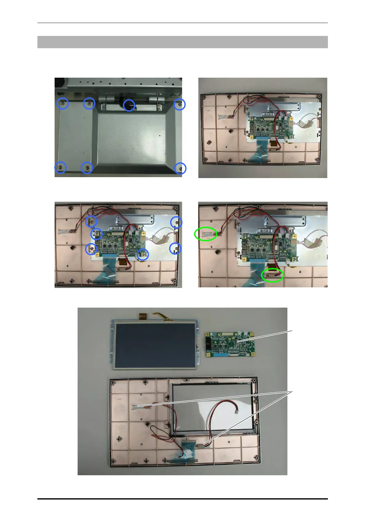
1.
Remove the seven fixing screws located on
the bottom of the operation panel.
2.
Remove the bottom case of the operation
panel.
3.
Unplug all harnesses and remove the fixing
screws to detach the touch panel LCD with
the bracket.
4.
Unplug the harnesses and peel off the
vibrator attached with the double-faced tape.
Bottom case
Display/
Key control board
PK-261
Vibrator
5-4 UNI-7 Service Manual