Chapter 5 MACHINE DISASSEMBLY
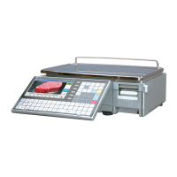
7.
Unplug the harness connected with the
display control board located inside of the
rear housing.
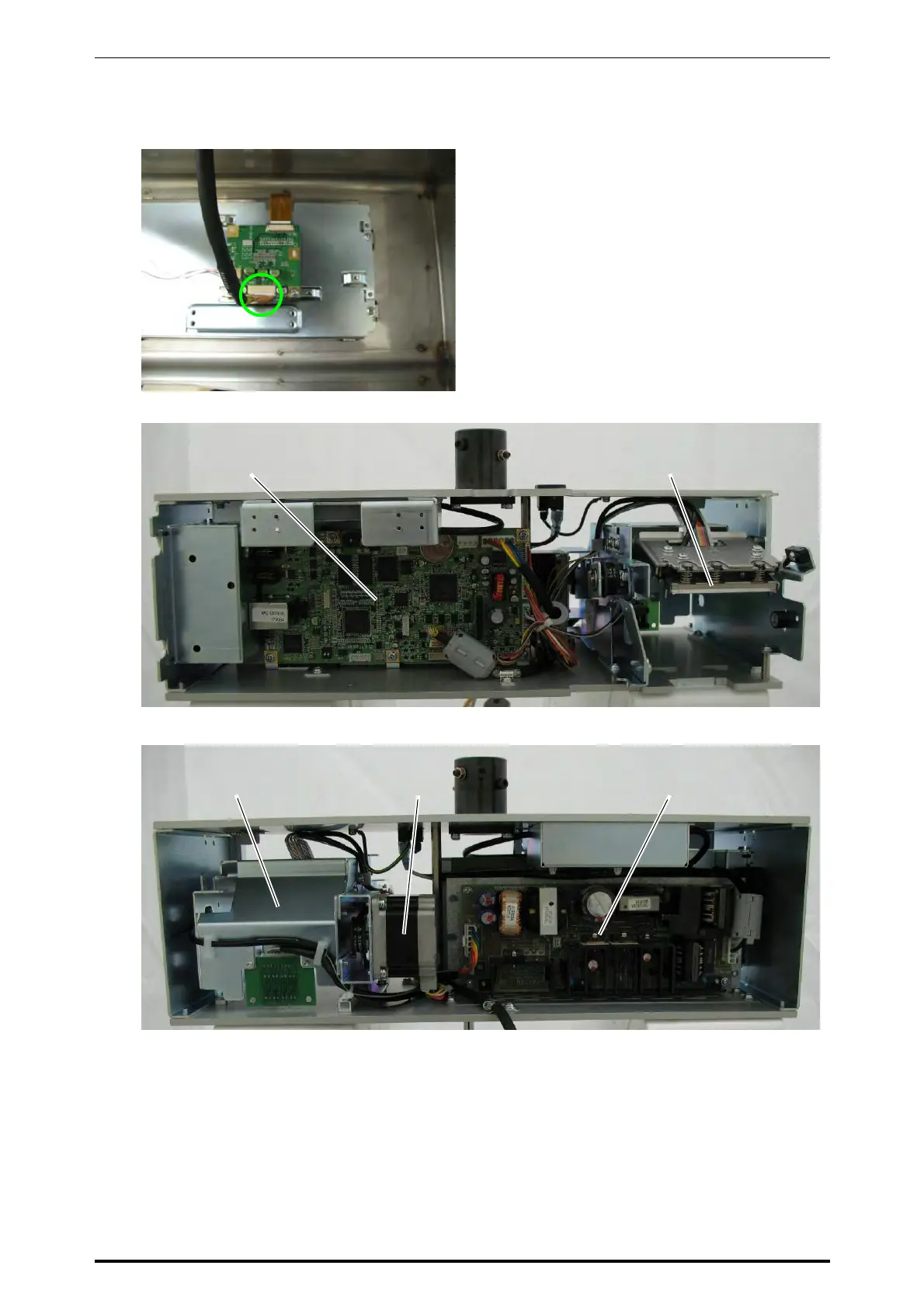
8.
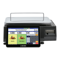
These photos show the front and rear views.
Main board
Printer unit
Motor unit
Printer unit
Power supply unit
* Reverse this procedure for assembly.
5-34 UNI-7 Service Manual