WhiletheaboveStandardRangeTestingprocedureis
recommended for most sport aircraft, for sophisticated
aircraftthatcontainsignificantamountsofconductive/
reflective materials (e.g. turbine-powered jets, some
types of scale aircraft, aircraft with carbon fuselages, etc.)
the following advanced range check will confirm that all
internal and remote receivers are operating optimally
and that the installation (position of the receivers) is
optimizedforthespecificaircraft.ThisAdvancedRange
Check allows you to evaluate the RF performance of each
individual internal and remote receiver and to optimize the
locations of each individual remote receiver.
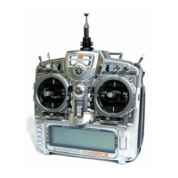
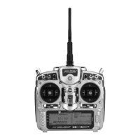
Advanced Range Testing the X9503 2.4
1. Plugaflightlog(optional)intothedataportintheJR
R921receiverandturnonthesystem(transmitterand
receiver).
2. AdvancetheFlightLoguntilF-framelossesare
displayed, by pressing the button on the flight log.
3. Haveahelperholdyouraircraftwhilehe/sheobserves
theFlightLogdata.
4. Standing 30 paces away from the model, face the
model with the transmitter in your normal flying
position. Depress and hold the bind button on the back
ofthetransmitter.Thiscausesreducedpoweroutput
from the transmitter.
5. Have your helper position the model in various
orientations (nose up, nose down, nose toward the
transmitter, nose away from the transmitter, etc.) while
yourhelperiswatchingtheFlightLog,notingany
correlation between the aircraft’s orientation and Frame
Losses.Dothisfor1minute.ThetimerontheX9503
canbeusedhere.Tiptheairplaneuponitsnoseand
rotateit360degreesforoneminute,thenrecordthe
data. Next place the airplane on its wheels and do a
second test, rotating the aircraft in all directions for
one minute.
6. Afteroneminute,releasethebindbutton.Asuccessful
range check will have recorded zero frame losses.
ScrolltheFlightLogthroughtheAntennafades
(A,B,L,R)toevaluatetheperformanceofeach
receiver. Antenna fades should be relatively uniform.
If a specific antenna is experiencing a high degree of
fades, then that antenna should be moved
to a different location.
7. A successful Advanced test will yield the following.
H - 0 holds
F - 0 frame losses
A,B,R,L-Antennafadeswilltypicallybelessthan100.
Compare the relative antenna fades and if a particular
receiver has significantly higher antenna fades (2 to 3X),
then the test should be redone. If the same results occur,
move the offending receiver to a different location.
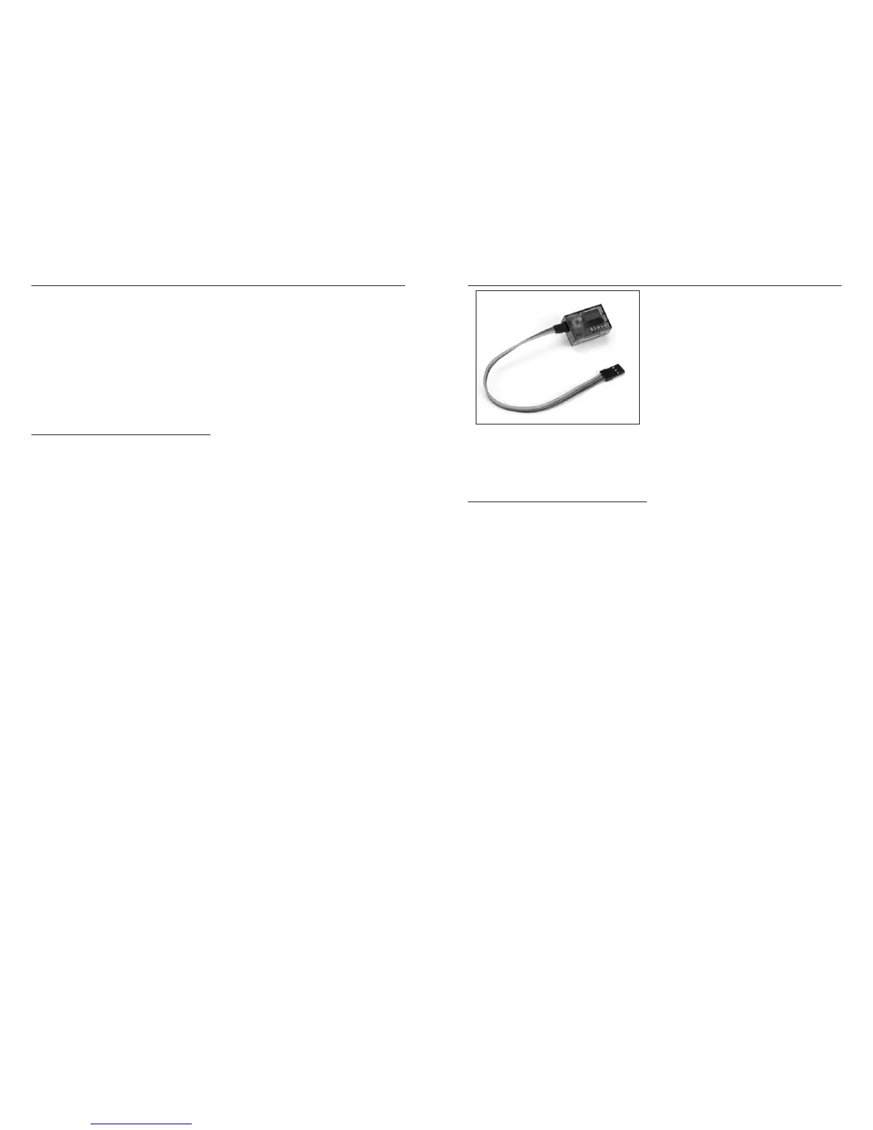
Advanced Range Testing Using a Flight Log
TheFlightLogiscompatiblewithJRR921receivers.The
FlightLogdisplaysoverallRFlinkperformanceaswell
as the individual internal and external receiver link data.
Additionally it displays receiver voltage.
Using the Flight Log
After a flight and before turning off the receiver or
transmitter,plugtheFlightLogintotheDataportonthe
JRR921receiver.Thescreenwillautomaticallydisplay
voltagee.g.6v2=6.2volts.
Note:Whenthevoltagereaches4.8voltsorless,
the screen will flash indicating low voltage.
Press the button to display the following information.
A - Antenna fades on internal antenna A
B-AntennafadesoninternalantennaB
L-Antennafadesontheleftexternalantenna
R - Antenna fades on the right external antenna
F - Frame loss
H - Holds
Antennafades—representsthelossofabitofinformation
on that specific antenna.
Typicallyit’snormaltohaveasmanyas50to100antenna
fades during a flight.
If any single antenna experiences over 500 fades in a
single flight, the antenna should be repositioned in the
aircraft to optimize the RF link.
Frameloss—representssimultaneousantennafades
on all attached receivers. If the RF link is performing
optimally, frame losses per flight should be less than 20.
A hold occurs when 45 continuous (one right after the
other) frame losses occur.
Thistakesaboutonesecond.Ifaholdoccursduring
a flight, you should re-evaluate the system. Move the
antennastodifferentlocationsand/orchecktobesurethe
transmitter and receivers are all working correctly.
Note:Aservoextensioncanbeusedtoallowthe
FlightLogtomoreconvenientlybepluggedinwithout
having to remove the aircraft’s hatch or canopy. On
somemodels,theFlightLogcanbepluggedin,
attached and left on the model using double-sided
tape.Thisiscommonwithhelicopters,mountingthe
FlightLogconvenientlytothesideframe.
Flight Log—Optional for JR R921 Receiver
 Loading...