The Elevator should move slightly downward when the
throttle is set to idle. If the Elevator moves upward,
change the +3% to a –3% to reverse the direction that
the Elevator travels. The Elevator can be made to move
more by increasing the percentage (more negative
or more positive) and move less by decreasing the
percentage. After test flying the aircraft, adjust the
percentage as may be necessary. Leave the upper value
of the selected position at 0% because there is to be
no Elevator input above idle.
7. Offset. Highlight and select OFFSET and set the
value to -140 to -160. This represents a throttle stick
position that is about 2–3 clicks up from full low
stick. This is also the point where the mixer causes
the Elevator to deflect the +3% set in the lower
position value. Above this position there is no Elevator
deflection and the Elevator returns to normal.
8. Verify Operation. Highlight and select the position
containing the +3% value using the Selector, move
the Gear switch to the ON position, and move the
throttle stick upwards from idle while observing the
position values. When the stick is brought down to
idle, the lower Pos0 value is highlighted indicating the
down Elevator deflection (+3%). Verify that the Elevator
is deflecting downward slightly. When the stick is
advanced above idle, the upper value is highlighted
(0%) and the Elevator returns to normal (no mixing).
Now turn the Gear switch to the OFF position. Note
the number next to the Program Mix Name is now
changed, indicating the mixer is looking at the values
in the other position. Since both of the values in this
position are at 0% there is no deflection of the Elevator
– the mixer is turned OFF regardless of throttle stick
position. Verify that the Elevator does not move when
the throttle stick is moved.
Note: To completely disable or otherwise
inhibit a mixer, highlight either the Master or
Slave and press the CLR button.
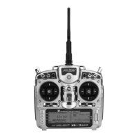
The example below demonstrates a Multi-Point Program
Mix for aircraft that pitches toward the landing gear
when holding Rudder for knife-edge flight – commonly
known as Pitch-Coupling. If a mix is set up to provide an
appropriate amount of up Elevator for different amounts of
Rudder input, the aircraft will fly straight without pitching
to the landing gear while holding Rudder during knife-
edge flight.
This Multi-Point mixer uses the Rudder as the Master and
the Elevator as the Slave. The mix is turned on and off
with the GEAR switch.
The Mix parameters will be selected and set in the
following order: Program Mix number, Master, Slave,
Switch, Set Points Travel/Direction, and Offset. This is
generally a good sequence to follow when setting up
Multi-Point Programmable Mixers.
1. Program Mix Number. Highlight and select one
of the Multi-Point Programmable Mixers (PROG.
MIX1 or PROG.MIX2) to obtain the first Multi-Point
Programmable Mix display. Then press ACT next to
CLR or highlight and select INH to obtain the main
mix display. The example is using PROG.MIX1.
2. Select Master. All Programmable Mixers default
to Throttle as both the Master and the Slave
(THROTHRO). The first THRO is the Master and
the 2nd THRO is the Slave.
Highlight and select the first THRO to the left of the
arrow to obtain a list of channels and select RUDD
as the Master.
3. Select Slave. Highlight and select THRO to the
right of the arrow to obtain a list of channels that
can be used as the Slave. Highlight and select ELEV
as the Slave.
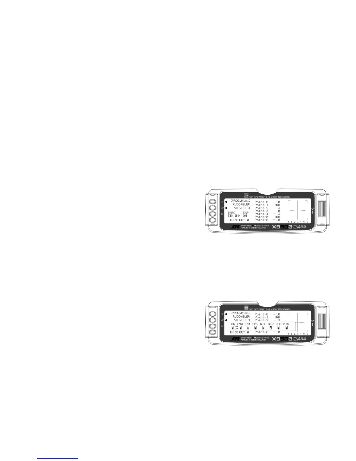
4. Select Switch. Scroll over to and select SW
SELECT to obtain a list of switches, then highlight
and select GER as the switch turning the mixer on
and off. The GER indicator should be in the upper or
ON position at the bottom of the display. You can use
any of the switches as well as multiple switches. The
example is using only the Gear switch.
 Loading...