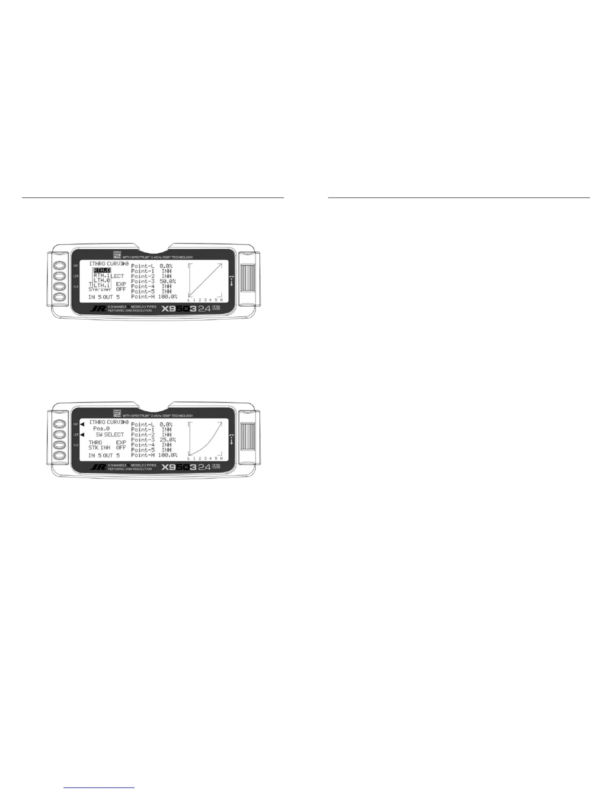
3. Scroll over to OFF under EXP and select it to turn
exponential ON. This smoothes out the throttle curve.
4. Scroll over to Point-3 and select it. Set the Point-3
value to 25%. This yields a preliminary throttle
curve that provides a good starting point for further
adjustments. The remainder of the adjustments should
be made with the engine running and the aircraft
securely restrained so that it cannot possibly move.
Note: If you activated Twin E. for a twin engine
aircraft, there will be a Pos0 and Pos1 for both the
right and left engines, providing a total of 4 possible
throttle curves.
5. Warm up the engine to its normal operating
temperature. Move the throttle stick to full idle and
slowly advance the throttle 1 click at a time. There
should be a noticeable change in rpm for each
movement of the stick. If while moving the stick it
seems that the engine should be running faster or
slower for a given throttle stick position, select the
point closest to the vertical line (cursor) and increase
the value if the engine is running too slow or decrease
the value if the engine is running too fast for the
stick position. Repeat as necessary until the desired
response is obtained.
However, instead of being named Pos0 & Pos1,
they are named RTH.0, RTH.1, LTH.0, and LTH.1.
They represent Right Throttle Pos0 & Pos1 and Left
Throttle Pos0 & Pos1 respectively.
The X9503 2.4 features a three-position Flap System
with Elevator compensation, programmable Delay, and
an Auto Land feature. Its purpose is to allow the flaps to
be deployed in two different positions in addition to the
normal or fully retracted position. The Flap System is
available in the FUNC.LIST only if SYS. is selected on the
OUT line under FLAP in the Devic. SEL function within the
SYSTEM Menu.
Because deploying flaps generally causes a change in
pitch (Elevator trim), the Flap System provides for setting
an Elevator deflection for each flap position. This is called
Elevator Compensation. There is also a programmable Delay
in .1 second increments up to a maximum of 2 seconds.
The Delay determines how long it takes for the Flaps and
Elevator to reach their positions. The X9503 2.4 ensures that
the Flaps and Elevator reach their positions at the same time
resulting in smooth Flap deployment and retraction.

 Loading...