1. Hold the ENT button while plugging the trainer cord
into the back of the transmitter to obtain the SYSTEM
Menu. Plug the other end of the trainer cord into
another X9503 2.4 transmitter while holding the ENT
button and prepare that transmitter for Transmit as
described above.
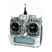
2. Highlight and select TRANSFER in the SYSTEM
Menu to obtain the Transfer display.
3. If RECEIVE is already displayed, continue with the
next step. If TRANSMIT is displayed, highlight and
select TRANSMIT, changing it to RECEIVE.
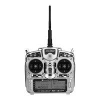
4. Select the model memory to receive the data by
highlighting and selecting the model name/memory
number. Then scroll to and select the model memory
that will receive the data. Be careful to select an unused
model memory or a model memory no longer needed
as the data in this model memory will be replaced and
permanently lost.
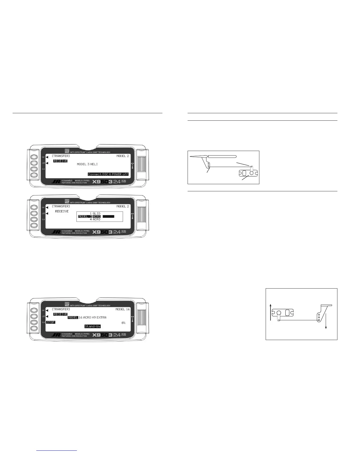
5. Press the CLR button next to START on the left side
of the display. Stand-by appears at the bottom of
the display indicating that the X9503 2.4 is ready to
receive data. Press start on the transmitting X9503 2.4
to begin the data transfer to the X9503 2.4.
Sub-Trims are intended for minor adjustments to servo
linkages and not for major trim adjustments to the aircraft.
Using excessive Sub-Trim percentages can cause a loss
in servo travel in one direction, where the servo reaches
its travel limit and stops moving before the control stick is
fully deflected.
The diagram below illustrates an ideal servo/linkage setup
when the servo is at neutral (no Sub-Trim and digital
trims centered). Notice that the servo arm is positioned
at 90˚ or perpendicular to the servo. Also note that the
linkage or rod is attached at 90˚ to both the servo arm and
the control surface horn. This setup results in the same
amount of throw in both directions (0 differential throw).
If you can’t mount the servo parallel to the linkage/rod,
make sure the servo arm is at 90 degrees to the control
rod when the servo is at neutral.
Mechanical Advantage is a very important concept when
dealing with larger aircraft. It refers to the leverage that
the servo can exert on the control surface. Since the
control surfaces are rather large, it is important for the
servo to have enough mechanical advantage or leverage
to control them, regardless of the servo’s rated torque.
A large amount of torque is of little value if there is not
enough leverage to use it. Insufficient leverage can lead to
control surface flutter (usually a catastrophic event) and
blow-back, where the air flow pushes the control surface
backwards resulting in mushy or no control at higher
speeds.
There are two ways to increase the mechanical advantage
of the servo. One is to make sure the control horn device,
whether it be a horn as shown in the illustration above or
a bolt with a ball-link fastener, is long enough. The horn
is the lever the servo uses to control the surface. The
longer the horn, the more leverage the servo has.
The second way to increase the mechanical advantage of
the servo is to attach the linkage at the servo arm as far
inward (toward the servo arm retaining screw) as possible
while still providing enough throw. This takes leverage
away from the control surface by providing it with a
shorter lever to work against the servo.
Ensure that the attach point is the same distance from the
hinge line for like surfaces (two Ailerons, two Elevators
and two Rudder horns). If the attach points are not the
same distance from the hinge line there will be unequal
throw and it will be more difficult to synchronize the
surfaces for equal deflection. This is especially critical
for the Rudder where two servos are attached to the same
surface – unequal throw will cause the servos to fight one
another causing excessive battery drain, and in severe
cases may cause servo damage.
Always try to use the maximum amount of Travel (100%)
the radio provides. Don’t reduce the percentage of travel in
the radio. Instead, move the linkage further away from the
hinge line at the control surface and/or move the linkage
inward on the servo arm or use a shorter arm. If you use
high percentages of travel, you maintain resolution (fine
movements of the stick result in fine positive movements
of the control surface).
Linkage is 90 degrees
to control horn
Linkage is 90 degrees to servo arm
Servo arm is 90 degrees to servo
Greater
Mechanical
Advantage
Greater
Mechanical
Advantage
 Loading...